THEFT DETERRENT SYSTEM > Security Horn Circuit |
| 1.PERFORM ACTIVE TEST USING INTELLIGENT TESTER (SECURITY HORN) |
Select the Active Test, use the intelligent tester to generate a control command, and then check that the security horn sounds.
| Item | Test Details | Diagnostic Note |
| Security Horn | Security horn ON/OFF | - |
|
| ||||
| OK | ||
| ||
| 2.INSPECT SECURITY HORN ASSEMBLY |
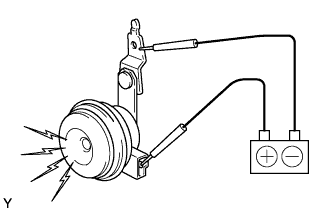 |
Remove the security horn.
Check operation of the horn.
| Measurement Condition | Specified Condition |
| Battery positive (+) → Terminal 1 Battery negative (-) → Horn bracket | Horn sounds |
|
| ||||
| OK | |
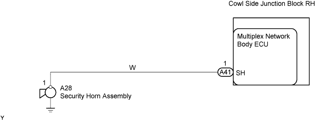
| 3.CHECK WIRE HARNESS (MULTIPLEX NETWORK BODY ECU - SECURITY HORN ASSEMBLY) |
 |
Disconnect the A41 ECU connector.
Disconnect the A28 horn connector.
Check the resistance of the wire harness side connectors.
| Tester Connection | Specified Condition |
| A41-1 (SH) - A28-1 | Below 1 Ω |
| A41-1 (SH) or A28-1 - Body sound | 10 kΩ or higher |
|
| ||||
| OK | ||
| ||
