OUTER REAR VIEW MIRROR > INSPECTION |
| 1. CHECK OUTER REAR VIEW MIRROR ASSEMBLY LH |
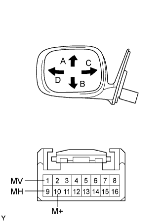 |
Apply battery voltage and check the operation of the mirror.
| Measurement Condition | Specified Condition |
| Battery positive (+) → Terminal 1 (MV) Battery negative (-) → Terminal 10 (M+) | Turns upward A |
| Battery positive (+) → Terminal 10 (M+) Battery negative (-) → Terminal 1 (MV) | Turns downward B |
| Battery positive (+) → Terminal 9 (MH) Battery negative (-) → Terminal 10 (M+) | Turns right C |
| Battery positive (+) → Terminal 10 (M+) Battery negative (-) → Terminal 9 (MH) | Turns left D |
 |
For each position:
Disconnect the battery, set the mirror position by hand, connect the battery, and check the retractable mirror's movement.
| Measurement Condition | Mirror Position | Specified Condition |
| Battery positive (+) → Terminal 3 (MR) Battery negative (-) → Terminal 11 (MF) | Forward position A | Moves from A to retracted position E |
| Battery positive (+) → Terminal 11 (MF) Battery negative (-) → Terminal 3 (MR) | Forward position A | Does not move |
| Battery positive (+) → Terminal 3 (MR) Battery negative (-) → Terminal 11 (MF) | Position between forward position A and driving position C | Moves from B to retracted position E |
| Battery positive (+) → Terminal 11 (MF) Battery negative (-) → Terminal 3 (MR) | Position between forward position A and driving position C | Moves from B to forward position A |
| Battery positive (+) → Terminal 3 (MR) Battery negative (-) → Terminal 11 (MF) | Driving position C | Moves from C to retracted position E |
| Battery positive (+) → Terminal 11 (MF) Battery negative (-) → Terminal 3 (MR) | Driving position C | Does not move |
| Battery positive (+) → Terminal 3 (MR) Battery negative (-) → Terminal 11 (MF) | Position between driving position C and retracted position E | Moves from D to retracted position E |
| Battery positive (+) → Terminal 11 (MF) Battery negative (-) → Terminal 3 (MR) | Position between driving position C and retracted position E | Moves from D to driving position C |
| Battery positive (+) → Terminal 3 (MR) Battery negative (-) → Terminal 11 (MF) | Retracted position E | Does not move |
| Battery positive (+) → Terminal 11 (MF) Battery negative (-) → Terminal 3 (MR) | Retracted position E | Moves from E to driving position C |
 |
Check the mirror position sensor.
Apply battery and dry cell battery voltage to the terminals as shown in the table below.
Measure the voltage while the mirror moves between the fully downward and fully upward positions.
| Measurement Condition (Battery) | Measurement Condition (Dry Cell Battery) | Voltmeter Condition | Mirror Condition | Specified Condition |
| Battery positive (+) → Terminal 10 (M+) Battery negative (-) → Terminal 1 (MV) | Battery positive (+) → Terminal 5 (VC) Battery negative (-) → Terminal 14 (E1) | Positive (+) lead → Terminal 6 (VSSL) Negative (-) lead → Terminal 14 (E1) | Turns fully downward | 0 to 1.0 V |
| Battery positive (+) → Terminal 1 (MV) Battery negative (-) → Terminal 10 (M+) | Battery positive (+) → Terminal 5 (VC) Battery negative (-) → Terminal 14 (E1) | Positive (+) lead → Terminal 6 (VSSL) Negative (-) lead → Terminal 14 (E1) | Turns fully upward | 2.8 to 5.0 V |
 |
Measure the voltage while the mirror moves between the fully turned to the left and fully turned to the right positions.
| Measurement Condition (Battery) | Measurement Condition (Dry Cell Battery) | Voltmeter Condition | Mirror Condition | Specified Condition |
| Battery positive (+) → Terminal 9 (MH) Battery negative (-) → Terminal 10 (M+) | Battery positive (+) → Terminal 5 (VC) Battery negative (-) → Terminal 14 (E1) | Positive (+) lead → Terminal 13 (HSSL) Negative (-) lead → Terminal 14 (E1) | Turns to left fully | 2.8 to 5.0 V |
| Battery positive (+) → Terminal 10 (M+) Battery negative (-) → Terminal 9 (MH) | Battery positive (+) → Terminal 5 (VC) Battery negative (-) → Terminal 14 (E1) | Positive (+) lead → Terminal 13 (HSSL) Negative (-) lead → Terminal 14 (E1) | Turns to right fully | 0 to 1.0 V |
 |
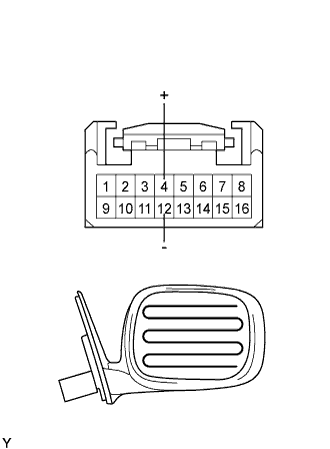
Check the mirror heater.
Measure the resistance between terminals 4 and 12 of the connector.
Apply battery voltage and check the operation of the mirror heater.
| Measurement Condition | Specified Condition |
| Battery positive (+) → Terminal 4 (+) Battery negative (-) → Terminal 12 (-) | Mirror becomes warm |
| 2. CHECK OUTER REAR VIEW MIRROR ASSEMBLY RH |
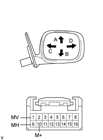 |
Apply battery voltage and check the operation of the mirror.
| Measurement Condition | Specified Condition |
| Battery positive (+) → Terminal 1 (MV) Battery negative (-) → Terminal 10 (M+) | Turns upward A |
| Battery positive (+) → Terminal 10 (M+) Battery negative (-) → Terminal 1 (MV) | Turns downward B |
| Battery positive (+) → Terminal 9 (MH) Battery negative (-) → Terminal 10 (M+) | Turns left C |
| Battery positive (+) → Terminal 10 (M+) Battery negative (-) → Terminal 9 (MH) | Turns right D |
 |
For each position:
Disconnect the battery, set the mirror position by hand, connect the battery, and check the retractable mirror's movement.
| Measurement Condition | Mirror Position | Specified Condition |
| Battery positive (+) → Terminal 3 (MR) Battery negative (-) → Terminal 11 (MF) | Forward position A | Moves from A to retracted position E |
| Battery positive (+) → Terminal 11 (MF) Battery negative (-) → Terminal 3 (MR) | Forward position A | Does not move |
| Battery positive (+) → Terminal 3 (MR) Battery negative (-) → Terminal 11 (MF) | Position between forward position A and driving position C | Moves from B to retracted position E |
| Battery positive (+) → Terminal 11 (MF) Battery negative (-) → Terminal 3 (MR) | Position between forward position A and driving position C | Moves from B to forward position A |
| Battery positive (+) → Terminal 3 (MR) Battery negative (-) → Terminal 11 (MF) | Driving position C | Moves from C to retracted position E |
| Battery positive (+) → Terminal 11 (MF) Battery negative (-) → Terminal 3 (MR) | Driving position C | Does not move |
| Battery positive (+) → Terminal 3 (MR) Battery negative (-) → Terminal 11 (MF) | Position between driving position C and retracted position E | Moves from D to retracted position E |
| Battery positive (+) → Terminal 11 (MF) Battery negative (-) → Terminal 3 (MR) | Position between driving position C and retracted position E | Moves from D to driving position C |
| Battery positive (+) → Terminal 3 (MR) Battery negative (-) → Terminal 11 (MF) | Retracted position E | Does not move |
| Battery positive (+) → Terminal 11 (MF) Battery negative (-) → Terminal 3 (MR) | Retracted position E | Moves from E to driving position C |
 |
Check the mirror position sensor.
Apply battery and dry cell battery voltage to the terminals as shown in the table below.
Measure the voltage while the mirror moves between the fully downward and fully upward positions.
| Measurement Condition (Battery) | Measurement Condition (Dry Cell Battery) | Voltmeter Condition | Mirror Condition | Specified Condition |
| Battery positive (+) → Terminal 10 (M+) Battery negative (-) → Terminal 1 (MV) | Battery positive (+) → Terminal 5 (VC) Battery negative (-) → Terminal 14 (E1) | Positive lead (+) → Terminal 6 (VSSL) Negative lead (-) → Terminal 14 (E1) | Turns fully downward | 0 to 1.0 V |
| Battery positive (+) → Terminal 1 (MV) Battery negative (-) → Terminal 10 (M+) | Battery positive (+) → Terminal 5 (VC) Battery negative (-) → Terminal 14 (E1) | Positive lead (+) → Terminal 6 (VSSL) Negative lead (-) → Terminal 14 (E1) | Turns fully upward | 2.8 to 5.0 V |
 |
Measure the voltage while the mirror moves between the fully turned to the left and fully turned to the right positions.
| Measurement Condition (Battery) | Measurement Condition (Dry Cell Battery) | Voltmeter Condition | Mirror Condition | Specified Condition |
| Battery positive (+) → Terminal 9 (MH) Battery negative (-) → Terminal 10 (M+) | Battery positive (+) → Terminal 5 (VC) Battery negative (-) → Terminal 14 (E1) | Positive lead (+) → Terminal 13 (HSSL) Negative lead (-) → Terminal 14 (E1) | Turns to left fully | 0 to 1.0 V |
| Battery positive (+) → Terminal 10 (M+) Battery negative (-) → Terminal 9 (MH) | Battery positive (+) → Terminal 5 (VC) Battery negative (-) → Terminal 14 (E1) | Positive lead (+) → Terminal 13 (HSSL) Negative lead (-) → Terminal 14 (E1) | Turns to right fully | 2.8 to 5.0 V |
 |
Check the mirror heater.
Measure the resistance between terminals 4 and 12 of the connector.
Apply battery voltage and check the operation of the mirror heater.
| Measurement Condition | Specified Condition |
| Battery positive (+) → Terminal 4 (+) Battery negative (-) → Terminal 12 (-) | Mirror becomes warm |
