POWER DOOR LOCK CONTROL SYSTEM > All Doors LOCK / UNLOCK Functions do not Operate Via Door Control Switch |
| 1.INSPECT FUSE (FR DOOR RH*1, FR DOOR LH*2, MPX-B, D/C CUT) |
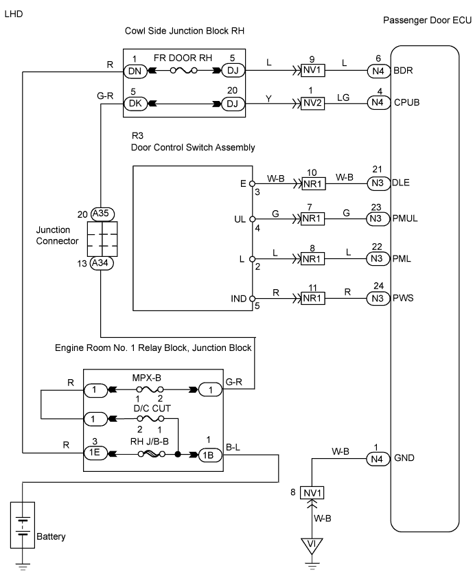
Remove the FR DOOR RH*1 fuse from the cowl side junction block RH.
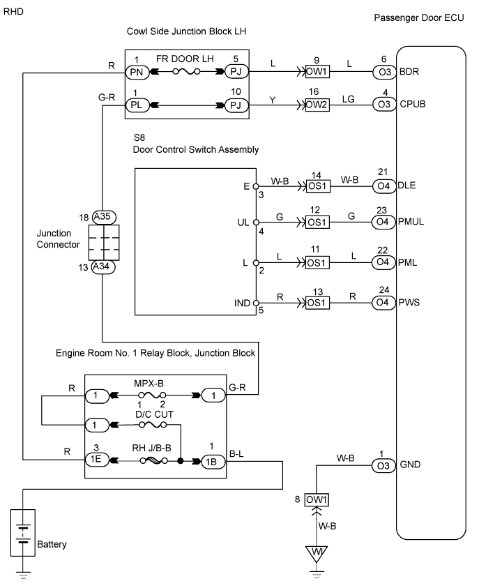
Remove the FR DOOR LH*2 fuse from the cowl side junction block LH.
Remove the MPX-B and D/C CUT fuses from the engine room No. 1 junction block.
Measure the resistance of the fuses.
|
| ||||
| OK | |
| 2.CHECK WIRE HARNESS (PASSENGER DOOR ECU - BATTERY AND BODY GROUND) |
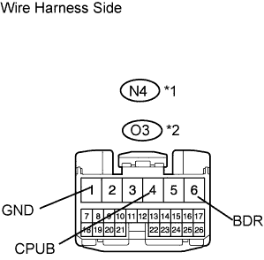 |
Disconnect the N4*1 or O3*2 ECU connector.
Measure the voltage of the wire harness side connector.
| Tester Connection | Specified Condition |
| N4-6 (BDR) - N4-1 (GND) | 10 to 14 V |
| N4-4 (CPUB) - N4-1 (GND) | 10 to 14 V |
| Tester Connection | Specified Condition |
| O3-6 (BDR) - O3-1 (GND) | 10 to 14 V |
| O3-4 (CPUB) - O3-1 (GND) | 10 to 14 V |
Measure the resistance of the wire harness side connector.
| Tester Connection | Specified Condition |
| N4-1 (GND) - Body ground | Below 1 Ω |
| Tester Connection | Specified Condition |
| O3-1 (GND) - Body ground | Below 1 Ω |
|
| ||||
| OK | |
| 3.INSPECT DOOR CONTROL SWITCH ASSEMBLY |
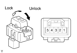 |
Remove the door control switch.
Measure the resistance of the switch.
| Tester Connection | Condition | Specified Condition |
| 2 - 3 | Lock | Below 1 Ω |
| 4 - 3 | Unlock | Below 1 Ω |
| 2 - 3 | Unlock | 10 kΩ or higher |
| 4 - 3 | Lock | 10 kΩ or higher |
|
| ||||
| OK | |
| 4.CHECK WIRE HARNESS (DOOR CONTROL SWITCH ASSEMBLY - PASSENGER DOOR ECU) |
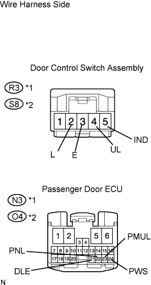 |
Disconnect the R3*1 or S8*2 switch connector.
Disconnect the N3*1 or O4*2 ECU connector.
Measure the resistance of the wire harness side connectors.
| Tester Connection | Specified Condition |
| R3-3 (E) - N3-21 (DLE) | Below 1 Ω |
| R3-4 (UL) - N3-23 (PMUL) | Below 1 Ω |
| R3-2 (L) - N3-22 (PNL) | Below 1 Ω |
| R3-5 (IND) - N3-24 (PWS) | Below 1 Ω |
| Tester Connection | Specified Condition |
| S8-3 (E) - O4-21 (DLE) | Below 1 Ω |
| S8-4 (UL) - O4-23 (PMUL) | Below 1 Ω |
| S8-2 (L) - O4-22 (PNL) | Below 1 Ω |
| S8-5 (IND) - O4-24 (PWS) | Below 1 Ω |
|
| ||||
| OK | |
| 5.REPLACE PASSENGER DOOR ECU |
After replacing the passenger door ECU with a normal one, check that all doors can be locked and unlocked by using the door control switch.
|
| ||||
| OK | ||
| ||
