POWER DOOR LOCK CONTROL SYSTEM > Key Lock-in Prevention Function does not Work Properly (Manual Operation and Key-Linked Lock are Activated) |

| 1.CHECK ENTRY AND START SYSTEM |
Check that each function of the entry door lock operates normally by using the lock switch.
|
| ||||
| OK | |
| 2.READ VALUE OF INTELLIGENT TESTER (FRONT DOOR COURTESY LIGHT SWITCH ASSEMBLY (DRIVER SIDE)) |
Check the Data List for proper functioning of the door courtesy light switch.
| Item | Measurement Item/Display (Range) | Normal Condition | Diagnostic Note |
| D Door Courtesy SW | Driver side door courtesy light switch signal/ON or OFF | ON: Driver side door is unlocked OFF: Driver side door is locked | - |
|
| ||||
| OK | ||
| ||
| 3.INSPECT FRONT DOOR COURTESY LIGHT SWITCH ASSEMBLY (DRIVER SIDE) |
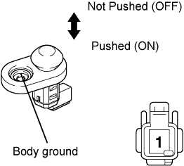 |
Remove the courtesy light switch.
Measure the resistance of the switch.
| Tester Connection | Switch Condition | Specified Condition |
| 1 - Body ground | Not pushed (ON) | Below 1 Ω |
| 1 - Body ground | Pushed (OFF) | 10 kΩ or higher |
|
| ||||
| OK | |
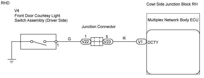
| 4.CHECK WIRE HARNESS (MULTIPLEX NETWORK BODY ECU - DOOR COURTESY LIGHT SWITCH) |
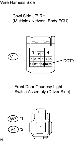 |
Disconnect the V1 ECU connector.
Disconnect the W7*1 or V4*2 switch connector.
Measure the resistance of the wire harness side connectors.
| Tester Connection | Specified Condition |
| V1-14 (DCTY) - W7-1 | Below 1 Ω |
| Tester Connection | Specified Condition |
| V1-14 (DCTY) - V4-1 | Below 1 Ω |
|
| ||||
| OK | ||
| ||
