POWER DOOR LOCK CONTROL SYSTEM > Only Rear Door RH LOCK / UNLOCK Functions do not Operate |
| 1.PERFORM ACTIVE TEST BY INTELLIGENT TESTER (REAR DOOR LOCK MOTOR) |
Select the Active test, use the intelligent tester to generate a control command, and then check that the door lock motor operates.
| Item | Test Details | Diagnostic Note |
| DOOR LOCK | Operate door lock motor LOCK/UNLOCK | - |
|
| ||||
| OK | ||
| ||
| 2.INSPECT FUSE (RR DOOR RH) |
Remove the RR DOOR RH fuse from the cowl side junction block RH.
Measure the resistance of the fuse.
|
| ||||
| OK | |
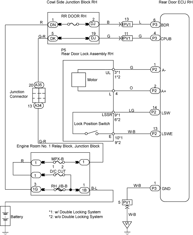
| 3.CHECK WIRE HARNESS (REAR DOOR ECU RH - BATTERY AND BODY GROUND) |
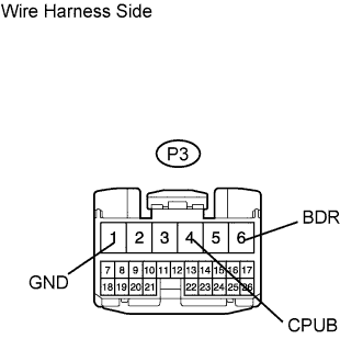 |
Disconnect the P3 ECU connector.
Measure the voltage of the wire harness side connector.
| Tester Connection | Specified Condition |
| P3-6 (BDR) - P3-1 (GND) | 10 to 14 V |
| P3-4 (CPUB) - P3-1 (GND) | 10 to 14 V |
Measure the resistance of the wire harness side connector.
| Tester Connection | Specified Condition |
| P3-1 (GND) - Body ground | Below 1 Ω |
|
| ||||
| OK | |
| 4.INSPECT REAR DOOR LOCK ASSEMBLY RH |
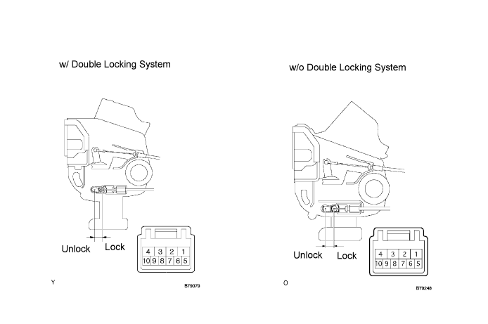
Apply battery voltage to the door lock motor and check the operation of the door lock motor.
| Measurement Condition | Specified Condition |
| Battery positive (+) → Terminal 4 Battery negative (-) → Terminal 3 | Lock |
| Battery positive (+) → Terminal 3 Battery negative (-) → Terminal 4 | Unlock |
| Measurement Condition | Specified Condition |
| Battery positive (+) → Terminal 4 Battery negative (-) → Terminal 1 | Lock |
| Battery positive (+) → Terminal 1 Battery negative (-) → Terminal 4 | Unlock |
|
| ||||
| OK | |
| 5.READ VALUE OF INTELLIGENT TESTER (DOOR LOCK POSITION SWITCH) |
Check the Data List for proper functioning of the door lock position switch.
| Item | Measurement Item/Display (Range) | Normal Condition | Diagnostic Note |
| Door Unlock Detection SW | Rear RH side door lock position switch signals/ON or OFF | ON: Rear RH side door is unlocked OFF: Rear RH side door is locked | - |
|
| ||||
| OK | ||
| ||
| 6.INSPECT REAR DOOR LOCK ASSEMBLY RH (DOOR LOCK POSITION SWITCH) |
Measure the resistance of the switch.
| Tester Connection | Switch Condition | Specified Condition |
| 9 - 10 | Unlock | Below 1 Ω |
| 9 - 10 | Lock | 10 kΩ or higher |
| Tester Connection | Switch Condition | Specified Condition |
| 6 - 9 | Unlock | Below 1 Ω |
| 6 - 9 | Lock | 10 kΩ or higher |
|
| ||||
| OK | |
| 7.CHECK WIRE HARNESS (REAR DOOR ECU RH - REAR DOOR LOCK ASSEMBLY RH) |
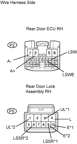 |
Disconnect the P2 ECU connector.
Disconnect the P5 door lock connector.
Measure the resistance of the wire harness side connectors.
| Tester Connection | Specified Condition |
| P2-1 (A-) - P5-3 (UL) | Below 1 Ω |
| P2-2 (A+) - P5-4 (L) | Below 1 Ω |
| P2-14 (LSW) - P5-9 (LSSR) | Below 1 Ω |
| P2-13 (LSWE) - P5-10 (E) | Below 1 Ω |
| Tester Connection | Specified Condition |
| P2-1 (A-) - P5-1 (UL) | Below 1 Ω |
| P2-2 (A+) - P5-4 (L) | Below 1 Ω |
| P2-14 (LSW) - P5-6 (LSSR) | Below 1 Ω |
| P2-13 (LSWE) - P5-9 (E) | Below 1 Ω |
|
| ||||
| OK | ||
| ||
