LIGHTING SYSTEM > AFS ECU Power Source Circuit |

| 1.CHECK AFS ECU |
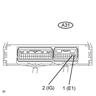 |
Measure the voltage of the connector.
| Tester Connection | Condition | Specified Condition |
| A31-1 - A31-2 | Engine switch off | Below 1 V |
| A31-1 - A31-2 | Engine switch on (IG) | 10 to 14 V |
|
| ||||
| OK | ||
| ||
| 2.CHECK WIRE HARNESS (AFS ECU - BODY GROUND) |
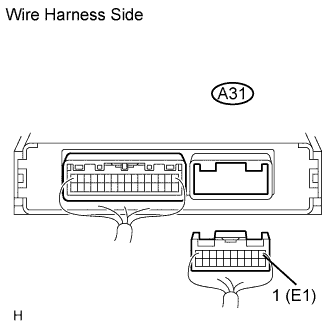 |
Disconnect the A31 AFS ECU connector.
Measure the resistance of the wire harness side connector.
| Tester Connection | Condition | Specified Condition |
| A31-1 - Body ground | Always | Below 1 Ω |
|
| ||||
| NG | ||
| ||
