DTC P0766 Shift Solenoid "D" Performance (Shift Solenoid Valve S4) |
| DTC No. | DTC Detection Condition | Trouble Area |
| P0766 |
|
|
| ECM command gearshift | 1st | 2nd | 3rd | 4th | 5th | 6th |
| *1: Actual gear position under malfunction | ↑ | ↑ | ↑ | ↑ | 4th | 4th |
| Gear position under normal conditions | 1st | 2nd | 3rd | 4th | 5th | 6th |
| *1: Actual gear position under fail-safe mode | ↑ | ↑ | ↑ | 3rd | 3rd | 3rd |
| ACTIVE TEST |
Warm up the engine.
Turn the engine switch off.
Connect the intelligent tester to the DLC3.
Turn the engine switch on (IG) Position.
Turn on the tester.
Select the item "Enter / Power train / ECT / Active Test".
Follow the instructions on the tester and read the Active Test.
| Item | Test Details | Diagnostic Note |
| Control the Shift Position | [Test Details] Operate the shift solenoid valve and set the each shift position by yourself. [Vehicle Condition]
| Possible to check the operation of the shift solenoid valves. |
| ECM command gearshift | 1st | 2nd | 3rd | 4th | 5th | 6th |
| Shift solenoid valve S4 | OFF | OFF | OFF | OFF | ON | ON |
| Shift solenoid valve SL2 | ON | ON | ON | ON | OFF | OFF |
| 1.CHECK OTHER DTCS OUTPUT (IN ADDITION TO DTC P0766) |
Connect the intelligent tester to the DLC3.
Turn the engine switch on (IG) position.
Turn on the tester.
Select the item "Power train / ECT / DTC / Current or Pending".
Read the DTCs using the intelligent tester.
| Display (DTC output) | Proceed to |
| Only "P0766" is output | A |
| "P0766" and other DTCs | B |
|
| ||||
| A | |
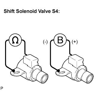
| 2.INSPECT SHIFT SOLENOID VALVE S4 |
 |
Remove the shift solenoid valve S4.
Measure the resistance according to the value(s) in the table below.
| Tester Connection | Specified Condition 20°C (68°F) |
| Solenoid Connector (S4) - Solenoid Body (S4) | 11 to 15 Ω |
Connect the positive (+) lead to the terminal of the solenoid connector, and the negative (-) lead to the solenoid body.
|
| ||||
| OK | |
| 3.INSPECT SHIFT SOLENOID VALVE SL2 |
 |
Remove the shift solenoid valve SL2.
Measure the resistance according to the value(s) in the table below.
| Tester Connection | Specified Condition 20°C (68°F) |
| 1 - 2 | 5.0 to 5.6 Ω |
Connect the positive (+) lead with a 21 W bulb to terminal 2 and the negative (-) lead to terminal 1 of the solenoid valve connector, then check the movement of the valve.
|
| ||||
| OK | |
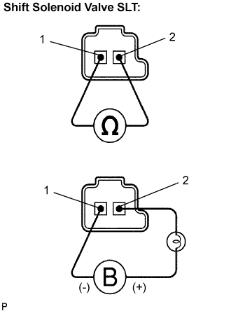
| 4.INSPECT SHIFT SOLENOID VALVE SLT |
 |
Remove the shift solenoid valve SLT.
Measure the resistance according to the value(s) in the table below.
| Tester Connection | Specified Condition 20°C (68°F) |
| 1 - 2 | 5.0 to 5.6 Ω |
Connect the positive (+) lead with a 21 W bulb to terminal 2 and the negative (-) lead to terminal 1 of the solenoid valve connector, then check the movement of the valve.
|
| ||||
| OK | |
| 5.INSPECT TRANSMISSION VALVE BODY ASSEMBLY |
|
| ||||
| OK | ||
| ||
