DTC    P0724    Brake Switch "B" Circuit High

for Preparation Click here


DESCRIPTION

The purpose of this circuit is to prevent the engine from stalling while driving in lock-up condition when brakes are suddenly applied.
When the brake pedal is depressed, this switch sends a signal to the ECM. Then the ECM cancels the operation of the lock-up clutch while braking is in progress.

DTC No.
DTC Detection Condition
Trouble Area
P0724
The stop light switch remains ON even when the vehicle is driven in a STOP (less than 3 km/h (2 mph)) and GO (30 km/h (19 mph) or more) fashion 5 times. (2-trip detection logic).
  1. Short in stop light switch signal circuit
  2. Stop light switch
  3. ECM

MONITOR DESCRIPTION

This DTC indicates that the stop light switch remains on. When the stop light switch remains ON during "stop and go" driving, the ECM interprets this as a fault in the stop light switch and the MIL comes on and the ECM stores the DTC. The vehicle must stop (less than 3 km/h (2 mph)) and go (30 km/h (19 mph) or more) ten times for two driving cycles in order to detect a malfunction.

WIRING DIAGRAM

Click here.

INSPECTION PROCEDURE

1.READ VALUE OF DATA LIST (STP SIGNAL)

HINT:
Using the intelligent tester Data List allows switch, sensor, actuator and other item values to be read without removing any parts. Reading the Data List early in troubleshooting is one way to shorten labor time.

  1. Turn the engine switch off.

  1. Connect the intelligent tester to the DLC3.

  1. Turn the engine switch on (IG) position.

  1. Turn on the tester.

  1. Select the item "Enter / Power train / ECT / Data List".

  1. Follow the instructions on the tester and read the Data List.

    Standard:

    Item
    Measurement Item/
    Range (display)
    Normal Condition
    Stop light SW
    Stop light switch Status/
    ON or OFF
    1. Brake Pedal is depressed: ON
    2. Brake Pedal is depressed: OFF

    NOTICE:
    In the table above, the conditions listed under "Normal Condition" are reference conditions. Do not depend solely on these reference conditions when deciding whether a part is faulty or not.


OK
Go to step 3
NG


2.INSPECT STOP LIGHT SWITCH ASSEMBLY


    I013683E07
  1. Remove the stop light switch assembly.

  1. Measure the resistance according to the value(s) in the table below.

    Resistance:
    Switch position
    Tester Connection
    Specified Condition
    Switch pin free
    1 - 2
    Below 1 Ω
    Switch pin pushed in

    10 kΩ or higher
    Switch pin free
    3 - 4
    10 kΩ or higher
    Switch pin pushed in

    Below 1 Ω


NG
REPLACE STOP LIGHT SWITCH ASSEMBLY
OK


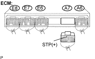
3.CHECK HARNESS AND CONNECTOR (STOP LIGHT SWITCH ASSEMBLY - ECM)


    C082160E07
  1. Install the stop light switch assembly.

  1. Disconnect the ECM connector.

  1. Measure the voltage according to the value(s) in the table below when the brake pedal is depressed and released.

    Voltage:
    Condition
    Tester Connection
    Specified Condition
    Brake pedal is depressed
    A7 - 4 (STP) - Body ground
    10 to 14 V
    Brake pedal is released

    Below 1 V


NG
REPAIR OR REPLACE HARNESS OR CONNECTOR
OK

REPLACE ECM