STEERING COLUMN ASSEMBLY (for 3UZ-FE) > INSTALLATION |
| 1. HANDLING PRECAUTIONS FOR STEERING ACTUATOR ASSEMBLY |
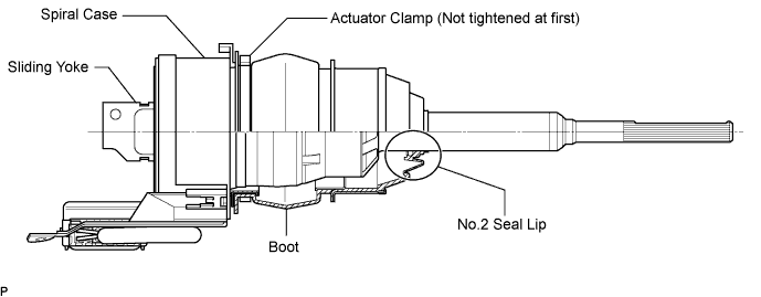
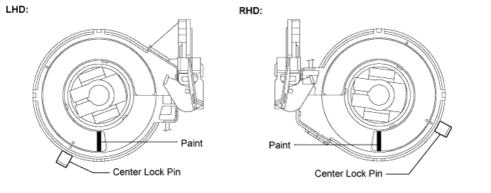
| 2. INSTALL STEERING ACTUATOR ASSEMBLY |
Make sure that the power steering link assembly is centered.
Install the steering actuator assembly.
If installing a new steering actuator assembly:
Install the steering actuator assembly with the white paint on the upper surface of the spiral case facing down.
If reinstalling the removed steering actuator assembly:
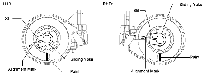
 |
 |
Install the clamp to the steering column hole shield.
| 3. INSTALL STEERING COLUMN ASSEMBLY |
 |
Install the steering column assembly with the 4 nuts.
Connect the connectors and wire harness clamps to the steering column assembly.
| 4. CONNECT STEERING ACTUATOR ASSEMBLY |
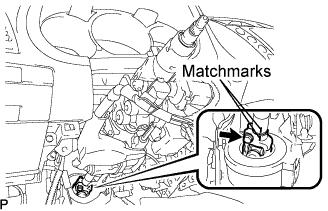 |
Align the matchmarks on the steering actuator assembly and the main shaft.
Install the bolt.
| 5. INSTALL STEERING SLIDING YOKE SUB-ASSEMBLY |
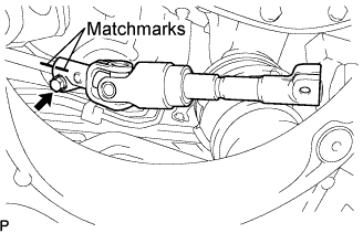 |
Align the matchmarks on the steering actuator assembly and the steering sliding yoke sub-assembly.
Temporarily install the bolt.
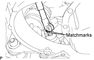 |
Align the matchmarks on the steering sliding yoke sub-assembly and the power steering link assembly.
 |
Install bolt (A) and tighten the 2 bolts.
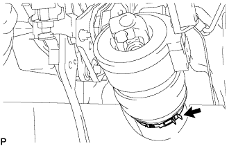
| 6. INSTALL MAIN SHAFT LOWER DUST COVER |
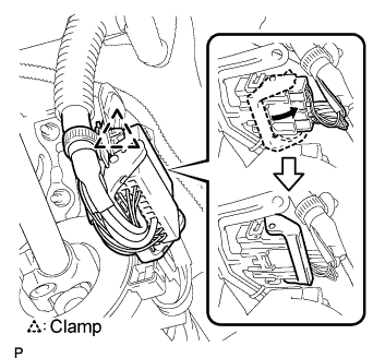 |
Connect the connector and wire harness clamp to the steering actuator assembly.
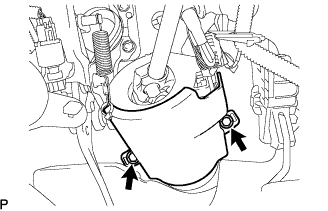 |
Install the main shaft lower dust cover with the 2 bolts.
| 7. PLACE FRONT WHEELS FACING STRAIGHT AHEAD |
| 8. INSTALL TURN SIGNAL SWITCH ASSEMBLY WITH SPIRAL CABLE SUB-ASSEMBLY |
 |
Install the turn signal switch assembly with spiral cable sub-assembly to the steering column assembly with the clamp.
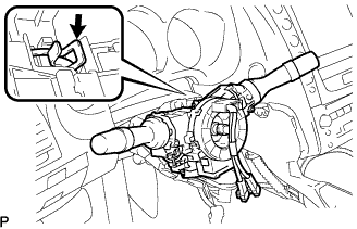
| 9. INSTALL TILT AND TELESCOPIC SWITCH |
 |
Engage the claw to install the tilt and telescopic switch.
Connect the connector.
| 10. INSTALL STEERING COLUMN COVER |
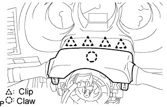 |
Engage the 4 clips to install the steering column cover upper onto the instrument panel cluster finish panel.
Engage the claw to install the steering column cover upper.
 |
Engage the 2 claws to install the steering column cover lower.
Using a socket wrench (+), install the 3 screws.
| 11. ADJUST SPIRAL CABLE SUB-ASSEMBLY |
Check that the engine switch is off.
Check that the battery negative (-) terminal is disconnected.
 |
Rotate the spiral cable with steering sensor counterclockwise slowly by hand until it feels firm.
 |
Rotate the spiral cable with steering sensor clockwise approximately 2.5 turns to align the marks.
| 12. INSTALL STEERING WHEEL ASSEMBLY |
Align the matchmarks on the steering wheel assembly and steering main shaft assembly.
Install the steering wheel assembly set nut.
| 13. INSPECT STEERING WHEEL CENTER POINT |
| 14. INSTALL AIR DUCT NO.1 |
Engage the 2 claws to install the air duct No.1.
| 15. INSTALL INSTRUMENT PANEL AIRBAG ASSEMBLY LOWER NO.1 |
 |
Connect the connector.
Install the driver side knee airbag assembly with the 4 bolts.
| 16. INSTALL INSTRUMENT PANEL SAFETY PAD SUB-ASSEMBLY NO.1 |
 |
Install the hood lock control cable to the safety pad.
Attach the 8 clips and claw to install the safety pad.
| 17. INSTALL INSTRUMENT PANEL UNDER COVER SUB-ASSEMBLY NO.1 |
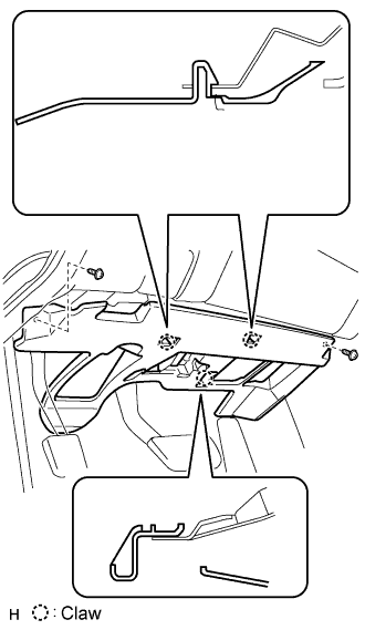 |
Connect the connectors.
Attach the 2 claws to install the under cover.
Install the 2 screws.
| 18. INSTALL INSTRUMENT SIDE PANEL LH |
 |
Attach the 2 claws and 4 clips to install the side panel.
| 19. INSTALL FRONT DOOR OPENING TRIM COVER LH |
Attach the 3 claws to install the trim cover.
Pull out the folded lip of the weatherstrip.
| 20. INSTALL FRONT DOOR SCUFF PLATE LH |
 |
Attach the 5 claws to install the scuff plate.
Pull out the folded lip of the weatherstrip.
| 21. INSTALL INSTRUMENT PANEL FINISH PANEL END LH |
 |
Attach the 4 clips and 3 claws to install the finish panel end.
Install the screw.
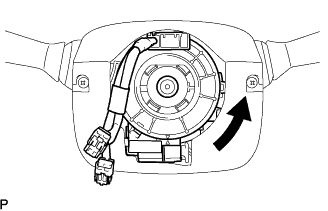
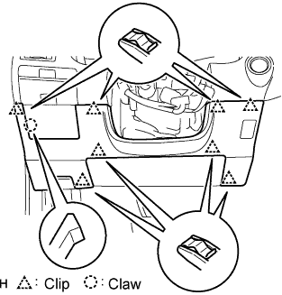
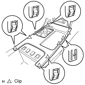
| 22. INSTALL CONSOLE UPPER PANEL SUB-ASSEMBLY |
 |
Connect the connector.
Attach the 9 clips to install the ash receptacle.
 |
Install the shift lever knob and twist it in the direction indicated by the arrow.
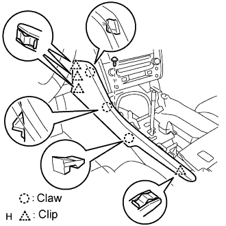
| 23. INSTALL CONSOLE UPPER PANEL GARNISH FRONT |
Attach the claws to install the garnish.
| 24. INSPECT STEERING WHEEL PAD |
 |
With the steering pad installed on the vehicle, perform a visual check. If there are any defects as mentioned below, replace the steering pad with a new one:
Make sure that the horn sounds.
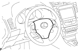
| 25. INSTALL STEERING WHEEL PAD |
 |
Support the steering pad with one hand as shown in the illustration.
Connect the 2 connectors to the steering pad.
Connect the horn connector.
 |
Confirm that the circumference groove of the "torx" screw fits in the screw case, and place the steering pad onto the steering wheel assembly.
Using a "torx" socket wrench (T30), tighten the 2 "torx" screws.
| 26. INSTALL STEERING WHEEL COVER LOWER NO.3 |
| 27. INSTALL STEERING WHEEL COVER LOWER NO.2 |
| 28. CONNECT CABLE TO NEGATIVE BATTERY TERMINAL |
| 29. INSPECT SRS WARNING LIGHT |
| 30. PERFORM INITIALIZATION |
| 31. PERFORM VARIABLE GEAR RATIO STEERING SYSTEM CALIBRATION |
