DTC P0420 Catalyst System Efficiency Below Threshold (Bank 1) |
DTC P0430 Catalyst System Efficiency Below Threshold (Bank 2) |
| DTC No. | DTC Detection Condition | Trouble Area |
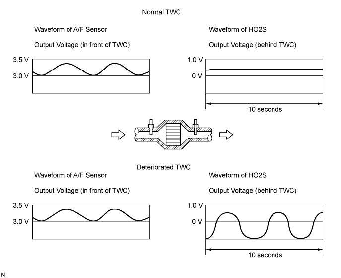
| P0420 | After engine and TWC warmed up, and while vehicle driven within set vehicle and engine speeds, waveform of Heated Oxygen (HO2) sensor (bank 1 sensor 2) alternates frequently between rich and lean (2 trip detection logic) |
|
| P0430 | After engine and catalyst are warmed up, and while vehicle is driven within set vehicle and engine speed ranges: Waveform of heated oxygen sensor (bank 2 sensor 2) alternates frequently between rich and lean (2 trip detection logic) |
|
| Case | A/F Sensor (Sensor 1) Output Voltage | HO2 Sensor (Sensor 2) Output Voltage | Main Suspected Trouble Area | ||
| 1 | Injection Volume +25 % -12.5 % |  | Injection Volume +25 % -12.5 % | | - |
| Output Voltage More than 3.35 V Less than 3.0 V |  | Output Voltage More than 0.55 V Less than 0.4 V |  | ||
| 2 | Injection Volume +25 % -12.5 % | | Injection Volume +25 % -12.5 % | |
|
| Output Voltage Almost no reaction |  | Output Voltage More than 0.55 V Less than 0.4 V | | ||
| 3 | Injection Volume +25 % -12.5 % | | Injection Volume +25 % -12.5 % | |
|
| Output Voltage More than 3.35 V Less than 3.0 V | | Output Voltage Almost no reaction | | ||
| 4 | Injection volume +25 % -12.5 % | | Injection Volume +25 % -12.5 % | |
|
| Output Voltage Almost no reaction | | Output Voltage Almost no reaction | | ||
| 1.CHECK ANY OTHER DTCS OUTPUT (IN ADDITION TO DTC P0420 AND/OR P0430) |
Connect the intelligent tester to the DLC3.
Turn the engine switch on (IG) and turn the tester ON.
Enter the following menus: Power train / Engine / DTC.
Read DTCs.
| Display (DTC output) | Proceed to |
| P0420 and/or P0430 | A |
| P0420 and/or P0430 and other DTCs | B |
|
| ||||
| A | |
| 2.PERFORM ACTIVE TEST USING INTELLIGENT TESTER (Control the Injection Volume for A/F Sensor) |
| Tester Display (Sensor) | Injection Volume | Status | Voltage |
| AFS B1 S1 or AFS B2 S1 (A/F) | +25 % | Rich | Less than 3.0 |
| AFS B1 S1 or AFS B2 S1 (A/F) | -12.5 % | Lean | More than 3.35 |
| O2S B1 S2 or O2S B2 S2 (HO2) | +25 % | Rich | More than 0.55 |
| O2S B1 S2 or O2S B2 S2 (HO2) | -12.5 % | Lean | Less than 0.4 |
| Status AFS B1 S1 or AFS B2 S1 | Status O2S B1 S2 or O2S B2 S2 | A/F Condition and A/F and HO2 Sensor Conditions | Misfire | Main Suspected Trouble Areas | Proceed to |
| Lean/Rich | Lean/Rich | Normal | - |
| A |
| Lean | Lean/Rich | A/F sensor malfunction | - |
| B |
| Rich | Lean/Rich | A/F sensor malfunction | May occur |
| B |
| Lean/Rich | Lean | HO2 sensor malfunction | - |
| C |
| Lean/Rich | Rich | HO2 sensor malfunction | - |
| C |
| Lean | Lean | Actual air-fuel ratio lean | May occur |
| A |
| Rich | Rich | Actual air-fuel ratio lean | - |
| A |
|
| ||||
|
| ||||
| A | |
| 3.CHECK FOR EXHAUST GAS LEAKAGE |
|
| ||||
| OK | ||
| ||
