CLEARANCE SONAR SYSTEM > DIAGNOSIS SYSTEM |
| DESCRIPTION |
DIAGNOSTIC SYSTEM
When troubleshooting a vehicle with the diagnosis system, the only difference from the usual troubleshooting procedure is connecting the intelligent tester to the vehicle and reading various data output from the vehicle's clearance warning ECU.
The clearance warning ECU records DTCs when the computer detects a malfunction in the computer itself or in its circuits.
To check the DTCs, connect the intelligent tester to the DLC3 on the vehicle. The intelligent tester enables you to erase the DTCs, activate the various actuators, and check the freeze frame data and Data List.
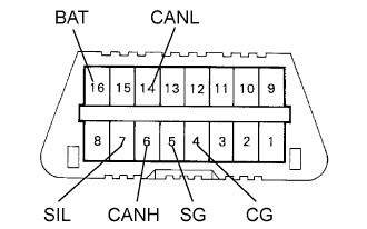 |
Check the DLC3.
The clearance warning ECU uses the ISO 15765-4 for communication protocol. The terminal arrangement of the DLC3 matches the ISO 15765-4 format.
| Symbols (Terminal No.) | Terminal Description | Condition | Specified Condition |
| SIL (7) - 5 (SG) | Bus "+" line | During communication | Pulse generation |
| CG (4) - Body ground | Chassis ground | Always | Below 1 Ω |
| SG (5) - Body ground | Signal ground | Always | Below 1 Ω |
| BAT (16) - Body ground | Battery positive | Always | 11 to 14 V |
| CANH (6) - CANL (14) | HIGH-level CAN bus line | Engine switch off | 54 to 67 Ω |
| CANH (6) - Battery positive | HIGH-level CAN bus line | Engine switch off | 1 MΩ or higher |
| CANH (6) - CG (4) | HIGH-level CAN bus line | Engine switch off | 3 KΩ or higher |
| CANL (14) - Battery positive | LOW-level CAN bus line | Engine switch off | 1 MΩ or higher |
| CANL (14) - CG (4) | LOW-level CAN bus line | Engine switch off | 3 KΩ or higher |
