MULTIPLEX COMMUNICATION SYSTEM > TERMINALS OF ECU |
| CHECK NETWORK GATEWAY ECU |
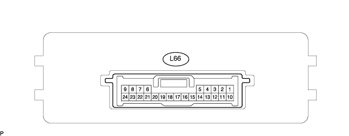
Disconnect the L66 ECU connector.
Measure the voltage and resistance of the wire harness side connector.
| Symbols (Terminal No.) | Wiring Color | Terminal Description | Condition | Specified Condition |
| BATT (L66-10) - GND (L66-24) | G - W-B | +B (BATT) power supply | Always | 10 to 14 V |
| IG (L66-1) - Body ground | B - Body ground | Ignition power supply | Engine switch on (IG) | 10 to 14 V |
| ACC (L66-2) - Body ground | V - Body ground | ACC power supply | Engine switch on (ACC) | 10 to 14 V |
| SIL (L66-7) - Body ground | O - Body ground | Bus ''+'' line | During transmission | Pulse generation |
| MPI1 (L66-4) - Body ground | LG - Body ground | MPX line | Always | 10 kΩ or higher |
| MPI2 (L66-13) - Body ground | GR - Body ground | MPX line | Always | 10 kΩ or higher |
| MPL1 (L66-5) - Body ground | W - Body ground | MPX line | Always | 10 kΩ or higher |
| MPL2 (L66-14) - Body ground | GR - Body ground | MPX line | Always | 10 kΩ or higher |
| MPD1 (L66-3) - Body ground | P - Body ground | MPX line | Always | 10 kΩ or higher |
| MPD2 (L66-12) - Body ground | SB - Body ground | MPX line | Always | 10 kΩ or higher |
| GND (L66-24) - Body ground | W-B - Body ground | Ground | Always | Below 1 Ω |
| CHECK ENGINE ROOM NO. 2 RELAY BLOCK (FRONT CONTROLLER) |

Disconnect the 2E and 2F junction block connectors.
Measure the voltage and resistance of the wire harness side connectors.
| Symbol (Terminal No.) | Wiring Color | Terminal Description | Condition | Specified Condition |
| FMB3 (2E-4) - E (2F-1) | G-R - W-B | +B (FMB3) power supply | Always | 10 to 14 V |
| MPX1 (2F-5) - E (2F-1) | GR-L*1, GR*2 - W-B | MPX line | Always | 10 kΩ or higher |
| MPX2 (2F-6) - E (2F-1) | GR-L - W-B | MPX line | Always | 10 kΩ or higher |
| E (2F-1) - Body ground | W-B - Body ground | Ground | Always | Below 1 Ω |
| CHECK COWL SIDE JUNCTION BLOCK LH (COWL SIDE JUNCTION BLOCK ECU LH) |
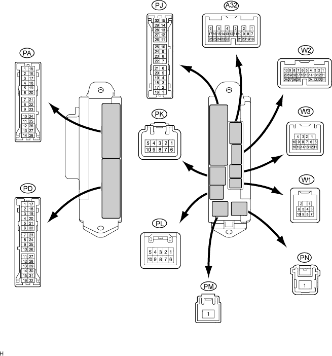
Disconnect the PA, PD and PL junction block connectors.
Disconnect the A32 and W3 ECU connectors.
Measure the resistance and voltage of the wire harness side connectors.
| Symbols (Terminal No.) | Wiring Color | Terminal Description | Condition | Specified Condition |
| MPX-B (PL-1) - GND (PA-14) | G-R - W-B | +B (MPX-B) power supply | Always | 10 to 14 V |
| MPX1 (W3-15) - Body ground | GR - Body ground | MPX line | Always | 10 kΩ or higher |
| MPX4 (A32-6) - Body ground | G-R - Body ground | MPX line | Always | 10 kΩ or higher |
| GND (PA-14) - Body ground | W-B - Body ground | Ground | Always | Below 1 Ω |
| SGND (PD-8) - Body ground | W-B - Body ground | Ground | Always | Below 1 Ω |
| CHECK COWL SIDE JUNCTION BLOCK RH (MULTIPLEX NETWORK BODY ECU) |
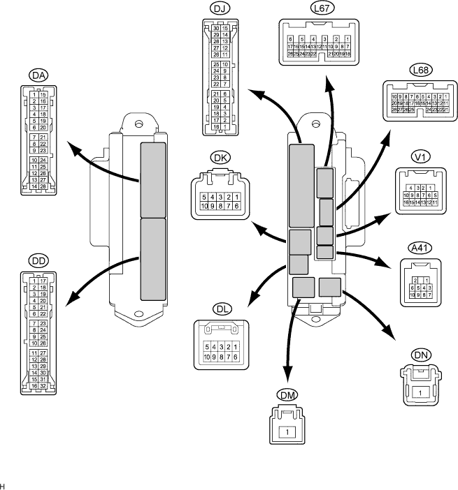
Disconnect the DA, DD and DK junction block connectors.
Disconnect the L68 ECU connector.
Measure the resistance and voltage of the wire harness side connectors.
| Symbols (Terminal No.) | Wiring Color | Terminal Description | Condition | Specified Condition |
| BECU (DK-5) - GND2 (DD-7) | G-R - W-B | +B (MPX-B) power supply | Always | 10 to 14 V |
| MPX1 (DA-26) - GND2 (DD-7) | GR - W-B | MPX line | Always | 10 kΩ or higher |
| MPX2 (L68-21) - GND2 (DD-7) | G*1, O*2 - W-B | MPX line | Always | 10 kΩ or higher |
| GSW (DA-7) - GND2 (DD-7) | B - W-B | MPX line | Always | 10 kΩ or higher |
| GND2 (DD-7) - Body ground | W-B - Body ground | Ground | Always | Below 1 Ω |
| CHECK NO. 1 JUNCTION BLOCK ASSEMBLY (MULTIPLEX NETWORK REAR ECU) |
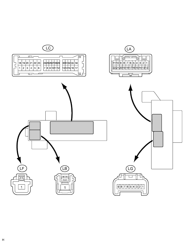
Disconnect the LB, LC and LF junction block connectors.
Measure the resistance and voltage of the wire harness side connectors.
| Symbols (Terminal No.) | Wiring Color | Terminal Description | Condition | Specified Condition |
| RFRL (LB-1) - Body ground | B - Body ground | +B (MPX-B) power supply | Always | 10 to 14 V |
| MPX1 (LC-21) - Body ground | BR - Body ground | MPX line | Always | 10 kΩ or higher |
| MPX2 (LC-31) - Body ground) | GR - Body ground | MPX line | Always | 10 kΩ or higher |
| P-GND (LF-1) - Body ground | W-B - Body ground | Ground | Always | Below 1 Ω |
| SG (LC-3) - Body ground | W-B - Body ground | Ground | Always | Below 1 Ω |
| CHECK MULTIPLEX NETWORK DOOR ECU FRONT LH (FRONT DOOR ECU LH) |
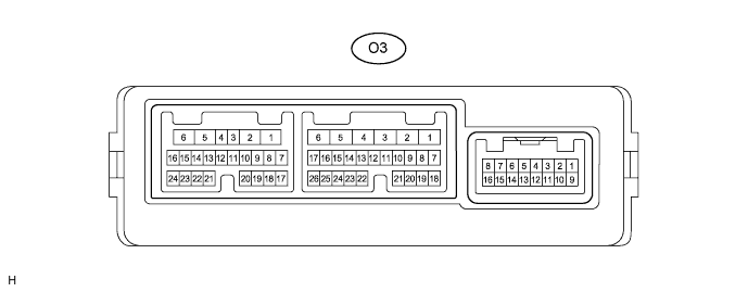
Disconnect the O3 ECU connector.
Measure the voltage and resistance of the wire harness side connector.
| Symbols (Terminal No.) | Wiring Color | Terminal Description | Condition | Specified Condition |
| CPUB (O3-4) - Body ground | LG - Body ground | +B (CPUB) power supply | Always | 10 to 14 V |
| BDR (O3-6) - Body ground | L - Body ground | +B (BDR) power supply | Always | 10 to 14 V |
| MPX1 (O3-8) - Body ground | P - Body ground | MPX line | Always | 10 kΩ or higher |
| MPX2 (O3-9) - Body ground | L - Body ground | MPX line | Always | 10 kΩ or higher |
| GND (O3-1) - Body ground | W-B - Body ground | Ground | Always | Below 1 Ω |
| CHECK MULTIPLEX NETWORK DOOR ECU FRONT RH (FRONT DOOR ECU RH) |
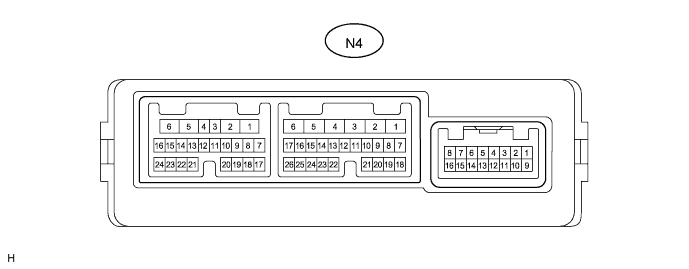
Disconnect the N4 ECU connector.
Measure the voltage and resistance of the wire harness side connector.
| Symbols (Terminal No.) | Wiring Color | Terminal Description | Condition | Specified Condition |
| CPUB (N4-4) - Body ground | LG - Body ground | +B (CPUB) power supply | Always | 10 to 14 V |
| BDR (N4-6) - Body ground | L - Body ground | +B (BDR) power supply | Always | 10 to 14 V |
| MPX1 (N4-8) - Body ground | GR - Body ground | MPX line | Always | 10 kΩ or higher |
| MPX2 (N4-9) - Body ground | P - Body ground | MPX line | Always | 10 kΩ or higher |
| GND (N4-1) - Body ground | W-B - Body ground | Ground | Always | Below 1 Ω |
| CHECK MULTIPLEX NETWORK DOOR ECU REAR LH (REAR DOOR LH) |
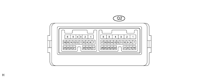
Disconnect the Q2 ECU connector.
Measure the voltage and resistance of the wire harness side connector.
| Symbols (Terminal No.) | Wiring Color | Terminal Description | Condition | Specified Condition |
| CPUB (Q2-4) - Body ground | BR - Body ground | +B (CPUB) power supply | Always | 10 to 14 V |
| BDR (Q2-6) - Body ground | L - Body ground | +B (BDR) power supply | Always | 10 to 14 V |
| MPX1 (Q2-8) - Body ground | GR - Body ground | MPX line | Always | 10 kΩ or higher |
| MPX2 (Q2-9) - Body ground | P - Body ground | MPX line | Always | 10 kΩ or higher |
| GND (Q2-1) - Body ground | W-B - Body ground | Ground | Always | Below 1 Ω |
| CHECK MULTIPLEX NETWORK DOOR ECU REAR RH (REAR DOOR RH) |
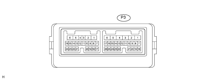
Disconnect the P3 ECU connector.
Measure the voltage the resistance of the wire harness side connector.
| Symbols (Terminal No.) | Wiring Color | Terminal Description | Condition | Specified Condition |
| CPUB (P3-4) - Body ground | G - Body ground | +B (CPUB) power supply | Always | 10 to 14 V |
| BDR (P3-6) - Body ground | L - Body ground | +B (BDR) power supply | Always | 10 to 14 V |
| MPX1 (P3-8) - Body ground | GR - Body ground | MPX line | Always | 10 kΩ or higher |
| MPX2 (P3-9) - Body ground | P - Body ground | MPX line | Always | 10 kΩ or higher |
| GND (P3-1) - Body ground | W-B - Body ground | Ground | Always | Below 1 Ω |
| CHECK POSITION CONTROL ECU AND SWITCH ASSEMBLY (DRIVER SIDE) |
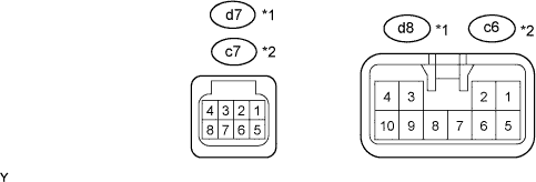
Disconnect the d7*1, c7*2 and d8*1, c6*2 ECU connectors.
Measure the voltage and the resistance of the wire harness side connectors.
| Symbols (Terminal No.) | Wiring Color | Terminal Description | Condition | Specified Condition |
| +B (d7-5)*1 - GND (d7-1)*1 | L - W-B | +B (+B) power supply | Always | 10 to 14 V |
| +B (c7-5)*2 - GND (c7-1)*2 | L - W-B | +B (+B) power supply | Always | 10 to 14 V |
| SYSB (d7-8)*1 - Body ground | G - Body ground | +B (SYSB) power supply | Always | 10 to 14 V |
| SYSB (c7-8)*2 - Body ground | R - Body ground | +B (SYSB) power supply | Always | 10 to 14 V |
| MPX1 (d7-1)*1 - Body ground | G-R - Body ground | MPX line | Always | 10 kΩ or higher |
| MPX1 (c7-1)*2 - Body ground | P - Body ground | MPX line | Always | 10 kΩ or higher |
| GND (d8-1)*1 - Body ground | W-B - Body ground | Ground | Always | Below 1 Ω |
| GND (c6-1)*2 - Body ground | W-B - Body ground | Ground | Always | Below 1 Ω |
| CHECK NO. 2 AIR CONDITIONING AMPLIFIER ASSEMBLY (A/C ECU) |
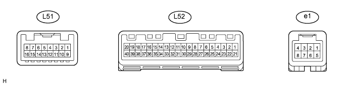
Disconnect the L52 amplifier connector.
Measure the voltage and resistance of the wire harness side connector.
| Symbols (Terminal No.) | Wiring Color | Terminal Description | Condition | Specified Condition |
| B (L52-1) - GND (L52-20) | L - W-B | +B power supply | Always | 10 to 14 V |
| IG+ (L52-21) - Body ground | W - Body ground | Engine switch signal (IG) | Engine switch on (IG) | 10 to 14 V |
| MPX+ (L52-30) - Body ground | SB - Body ground | MPX line | Always | 10 kΩ or higher |
| MPX- (L52-31) - Body ground | Y - Body ground | MPX line | Always | 10 kΩ or higher |
| GND (L52-20) - Body ground | W-B - Body ground | Ground | Always | Below 1 Ω |
| CHECK AIRBAG SENSOR ASSEMBLY CENTER |

Disconnect the L44 sensor connector.
Measure the voltage and resistance of the wire harness side connector.
| Symbols (Terminal No.) | Wiring Color | Terminal Description | Condition | Specified Condition |
| IG2 (L44-21) - E1(L44-25) | B - W-B | Engine switch signal (IG) | Engine switch on (IG) | 10 to 14 V |
| MPX1 (L44-13) - Body ground | R - Body ground | MPX line | Always | 10 kΩ or higher |
| MPX2 (L44-22) - Body ground | R - Body ground | MPX line | Always | 10 kΩ or higher |
| E1 (L44-25) - Body ground | W-B - Body ground | Ground | Always | Below 1 Ω |
| E2 (L44-26) - Body ground | W-B - Body ground | Ground | Always | Below 1 Ω |
| CHECK COMBINATION METER ASSEMBLY (METER ECU) |
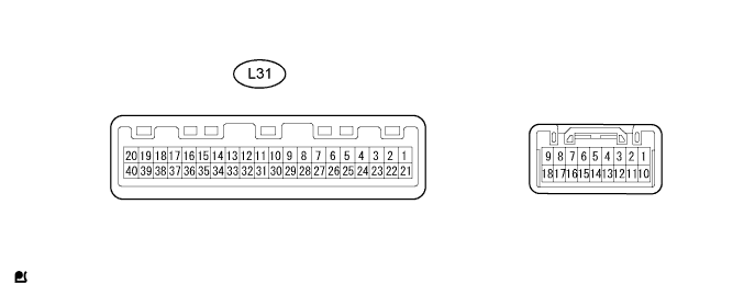
Disconnect the L31 meter connector.
Measure the voltage and resistance of the wire harness side connector.
| Symbols (Terminal No.) | Wiring Color | Terminal Description | Condition | Specified Condition |
| B (L31-21) - Body ground | B - Body ground | +B (B) power supply | Always | 10 to 14 V |
| B (L31-22) - Body ground | L - Body ground | +B (B) power supply | Always | 10 to 14 V |
| MPX+ (L31-25) - Body ground | GR - Body ground | MPX line | Always | 10 kΩ or higher |
| MPX- (L31-5) - Body ground | SB - Body ground | MPX line | Always | 10 kΩ or higher |
| E2 (L31-40) - Body ground | W-B - Body ground | Ground | Always | Below 1 Ω |
| CHECK SLIDING ROOF DRIVE GEAR SUB-ASSEMBLY (SLIDING ROOF CONTROL ECU) |

Disconnect the Y11 driver gear connector.
Measure the voltage and the resistance of the wire harness side connector.
| Symbols (Terminal No.) | Wiring Color | Terminal Description | Condition | Specified Condition |
| B (Y11-5) - E (Y11-7) | L - W-B | +B (B) power supply | Always | 10 to 14 V |
| MPX1 (Y11-10) - Body ground | GR - Body ground | MPX line | Always | 10 kΩ or higher |
| E (Y11-7) - Body ground | W-B - Body ground | Ground | Always | Below 1 Ω |
| CHECK MULTIPLEX TILT AND TELESCOPIC ECU |

Disconnect the L27 ECU connector.
Measure the voltage and resistance of the wire harness side connector.
| Symbols (Terminal No.) | Wiring Color | Terminal Description | Condition | Specified Condition |
| ECUB (L27-9) - GND (L27-11) | R - W-B | +B (ECUB) power supply | Always | 11 to 14 V |
| +B (L27-2) - GND (L27-11) | L - W-B | +B (+B) power supply | Always | 11 to 14 V |
| MPX1 (L27-5) - Body ground | GR - Body ground | MPX line | Always | 10 kΩ or higher |
| E (L27-11) - Body ground | W-B - Body ground | Ground | Always | Below 1 Ω |
| CHECK COMBINATION SWITCH ASSEMBLY (WINDSHIELD WIPER SWITCH) |

Disconnect the L22 switch connector.
Measure the voltage and resistance of the wire harness side connector.
| Symbols (Terminal No.) | Wiring Color | Terminal Description | Condition | Specified Condition |
| B (L22-1) - E (L22-5) | GR - W-B | +B (B) power supply | Always | 10 to 14 V |
| MPX1 (L22-6) - Body ground | G*1, O*2 - Body ground | MPX line | Always | 10 kΩ or higher |
| MPX2 (L22-7) - Body ground | O*1, G*2 - Body ground | MPX line | Always | 10 kΩ or higher |
| E (L22-5) - Body ground | W-B - Body ground | Ground | Always | Below 1 Ω |
| CHECK MULTIPLEX NETWORK MASTER SWITCH ASSEMBLY |
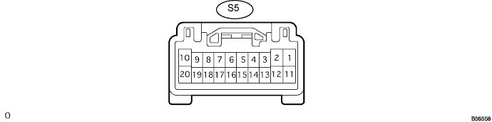
Disconnect the S5 switch connector.
Measure the voltage and resistance of the wire harness side connector.
| Symbols (Terminal No.) | Wiring Color | Terminal Description | Condition | Specified Condition |
| CPUB (S5-9) - E (S5-2) | G - W-B | +B (CPUB) power supply | Always | 10 to 14 V |
| E (S5-2) - Body ground | W-B - Body ground | Ground | Always | Below 1 Ω |
| MPX1 (S5-7) - E (S5-2) | GR - W-B | MPX line | Always | Below 1 Ω |
| MPX2 (S5-8) - E (S5-2) | P - W-B | MPX line | Always | Below 1 Ω |
| CHECK POWER SOURCE CONTROL ECU |

Disconnect the L73 ECU connector.
Measure the voltage and resistance of the wire harness side connector.
| Symbols (Terminal No.) | Wiring Color | Terminal Description | Condition | Specified Condition |
| AM1 (L73-33) - GND2 (L73-6) | O - W-B | +B power supply | Always | 10 to 14 V |
| AM2 (L73-12) - GND2 (L73-6) | BR - W-B | +B power supply | Always | 10 to 14 V |
| MPX1 (L73-7) - Body ground | LG - Body ground | MPX line | Always | 10 kΩ or higher |
| GND2 (L73-6) - Body ground | W-B - Body ground | Ground | Always | Below 1 Ω |
| CHECK CERTIFICATION ECU |

Disconnect the V28 ECU connector.
Measure the resistance and voltage of the wire harness side connector.
| Symbols (Terminal No.) | Wiring Color | Terminal Description | Condition | Specified Condition |
| +B1 (V28-1) - E (V28-17) | R - W-B | B power supply | Always | 10 to 14 V |
| MPX1 (V28-27) - E (V28-17) | BR - W-B | MPX line | Always | 10 kΩ or higher |
| MPX2 (V28-28) - E (V28-17) | GR - W-B | MPX line | Always | 10 kΩ or higher |
| E (V28-17) - Body ground | W-B - Body ground | Ground | Always | Below 1 Ω |
| CHECK TIRE PRESSURE WARNING ECU |
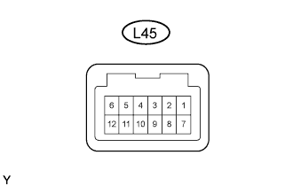
Disconnect the L45 ECU connector.
Measure the resistance and voltage of the wire harness side connector.
| Symbols (Terminal No.) | Wiring Color | Terminal Description | Condition | Specified Condition |
| IG (L45-1) - GND (L45-7) | G - W-B | Power supply | Always | 10 to 14 V |
| MPX1 (L45-6) - GND (L45-7) | LG - W-B | MPX line | Always | 10 kΩ or higher |
| MPX2 (L45-12) - GND (L45-7) | GR - W-B | MPX line | Always | 10 kΩ or higher |
| GND (L45-7 ) - Body ground | W-B - Body ground | Ground | Always | Below 1 Ω |
