LIGHTING SYSTEM > Headlight Relay Circuit |
| 1.PERFORM ACTIVE TEST BY INTELLIGENT TESTER |
Select the Active Test, use the intelligent tester to generate a control command, and then check that the headlight assembly (low) illuminates.
| Item | Tester Details | Diagnostic Note |
| Head Light | Headlight relay ON / OFF | - |
|
| ||||
| OK | ||
| ||
| 2.INSPECT FUSE (H-LP L LWR, H-LP R LWR) |
Remove the H-LP L LWR fuse from the engine room No. 2 relay block.
Remove the H-LP R LWR fuse from the engine room No. 2 relay block.
Measure the resistance of the fuses.
|
| ||||
| OK | |
| 3.INSPECT RELAY (Marking: HEAD LP) |
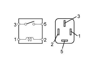 |
Remove the HEAD LP relay from the engine room No. 1 relay block.
Measure the resistance of the HEAD LP relay.
| Tester Connection | Specified Condition |
| 3 - 5 | 10 kΩ or higher |
| 3 - 5 | Below 1 Ω (When battery voltage is applied to terminals 1 and 2) |
|
| ||||
| OK | |
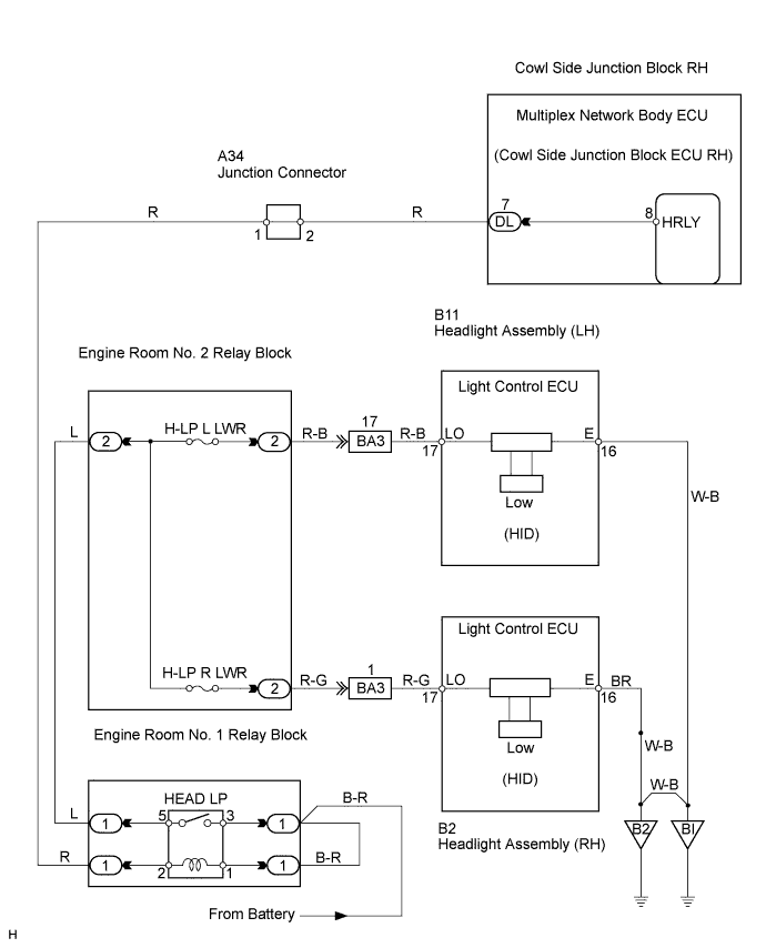
| 4.CHECK WIRE HARNESS (COWL SIDE JUNCTION BLOCK RH - BATTERY) |
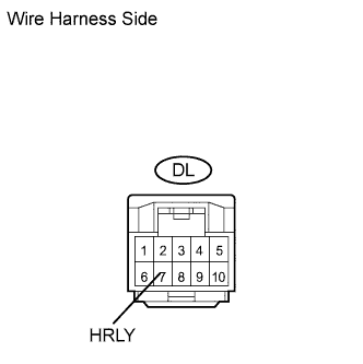 |
Disconnect the DL junction block connector.
Measure the voltage of the wire harness side connector.
| Tester Connection | Specified Condition |
| DL-7 (HEAD) - Body ground | 10 to 14 V |
|
| ||||
| OK | |
| 5.CHECK WIRE HARNESS (HEADLIGHT (LOW LH OR LOW RH) - BATTERY AND BODY GROUND) |
 |
Check the wire harness between the headlight (Low LH) and battery, and the headlight (Low LH) and body ground.
Disconnect the B11 light connector.
Turn the light control switch to the ON (HEAD) position.
Measure the voltage and resistance of the wire harness side connector.
| Tester Connection | Specified Condition |
| B11-17 (LO) - Body ground | 10 to 14 V |
| Tester Connection | Specified Condition |
| B11-16 (E) - Body ground | Below 1 Ω |
 |
Check the wire harness between the headlight (Low RH) and battery, and the headlight (Low RH) and body ground.
Disconnect the B2 light connector.
Turn the light control switch to the ON (HEAD) position.
Measure the voltage and resistance of the wire harness side connector.
| Tester Connection | Condition | Specified Condition |
| B2-17 (LO) - Body ground | Engine switch on (IG) | 10 to 14 V |
| Tester Connection | Specified Condition |
| B2-16 (E) - Body ground | Below 1 Ω |
|
| ||||
| OK | |
| 6.REPLACE HEADLIGHT ASSEMBLY (LOW LH OR LOW RH) |
Temporarily replace the headlight assembly (low LH or low RH) with a new or normally functioning one.
Check that the headlight assembly (low LH or low RH) illuminates.
|
| ||||
| NG | ||
| ||
