WINDOW DEFOGGER SYSTEM > TERMINALS OF ECU |
| CHECK ECM (3GR-FE, 3GR-FSE) |
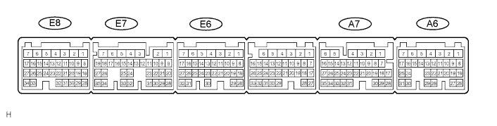
Measure the voltage and resistance of each terminal of the connectors.
| Symbols (Terminal No.) | Wiring Color | Terminal Description | Condition | Specified Condition |
| +BM (E8-5) - E1 (E7-7) | P - BR | Power supply | Engine switch on (IG) | 10 to 14 V |
| BATT (A6-4) - E1 (E7-7) | L - BR | Power supply | Always | 10 to 14 V |
| +B1 (A6-5) - E1 (E7-7) | B-R - BR | Power supply | Engine switch on (IG) | 10 to 14 V |
| +B (A6-6) - E1 (E7-7) | B-R - BR | Power supply | Engine switch on (IG) | 10 to 14 V |
| IGSW (A6-17) - E1 (E7-7) | B-W - BR | Ignition power supply | Engine switch on (IG) | Below 1 V |
| IGSW (A6-17) - E1 (E7-7) | B-W - BR | Ignition power supply | Engine switch off | 10 to 14 V |
| RDEF (A7-13) - E1 (E7-7) | G-B - BR | DEFOG relay | Engine switch on (IG) Rear defogger switch ON | Below 1 V |
| RDEF (A7-13) - E1 (E7-7) | G-B - BR | DEFOG relay | Engine switch on (IG) Rear defogger switch OFF | 10 to 14 V |
| ME01 (E8-4) - Body ground | W-B - Body ground | Ground | Always | Below 1 Ω |
| E1 (E7-7) - Body ground | BR - Body ground | Ground | Always | Below 1 Ω |
| E02 (E6-1) - Body ground | W-B - Body ground | Ground | Always | Below 1 Ω |
| E01 (E6-2) - Body ground | W-B - Body ground | Ground | Always | Below 1 Ω |
| EC (A6-2) - Body ground | W-B - Body ground | Ground | Always | Below 1 Ω |
| CHECK ECM (3UZ-FE) |
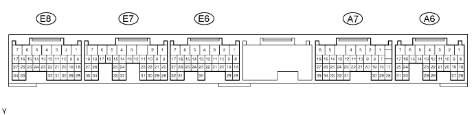
Measure the voltage and resistance of each terminal of the connectors.
| Symbols (Terminal No.) | Wiring Color | Terminal Description | Condition | Specified Condition |
| +BM (E8-5) - E1 (E7-7) | P - BR | Power supply | Engine switch on (IG) | 10 to 14 V |
| BATT (A6-4) - E1 (E7-7) | L - BR | Power supply | Always | 10 to 14 V |
| +B1 (A6-5) - E1 (E7-7) | B-R - BR | Power supply | Engine switch on (IG) | 10 to 14 V |
| +B (A6-6) - E1 (E7-7) | B-R - BR | Power supply | Engine switch on (IG) | 10 to 14 V |
| IGSW (A6-17) - E1 (E7-7) | B-W - BR | Ignition power supply | Engine switch on (IG) | Below 1 V |
| IGSW (A6-17) - E1 (E7-7) | B-W - BR | Ignition power supply | Engine switch off | 10 to 14 V |
| RDEF (A7-13) - E1 (E7-7) | G-B - BR | DEFOG relay | Engine switch on (IG) Rear defogger switch ON | Below 1 V |
| RDEF (A7-13) - E1 (E7-7) | G-B - BR | DEFOG relay | Engine switch on (IG) Rear defogger switch OFF | 10 to 14 V |
| ME01 (E8-4) - Body ground | BR - Body ground | Ground | Always | Below 1 Ω |
| E1 (E7-7) - Body ground | BR - Body ground | Ground | Always | Below 1 Ω |
| E02 (E6-1) - Body ground | W-B - Body ground | Ground | Always | Below 1 Ω |
| E01 (E6-2) - Body ground | W-B - Body ground | Ground | Always | Below 1 Ω |
| EC (A6-2) - Body ground | W-B - Body ground | Ground | Always | Below 1 Ω |
| CHECK A/C AMPLIFIER ASSEMBLY (A/C ECU) |

Disconnect the L52 amplifier connector.
Measure the voltage and resistance of the wire harness side connector.
| Symbols (Terminal No.) | Wiring Color | Terminal Description | Condition | Specified Condition |
| IG+ (L52-21) - GND (L52-20) | W - W-B | Ignition power supply | Engine switch on (IG) | 10 to 14 V |
| IG+ (L52-21) - GND (L52-20) | W - W-B | Ignition power supply | Engine switch off | Below 1 V |
| B (L52-1) - GND (L52-20) | L - W-B | Battery power supply | Always | 10 to 14 V |
| GND (L52-20) - Body ground | W-B - Body ground | Ground | Always | Below 1 Ω |
| CHECK MULTI-DISPLAY |
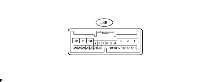
Disconnect the L46 multi-display connector.
Measure the voltage and resistance of the wire harness side connector.
| Symbols (Terminal No.) | Wiring Color | Terminal Description | Condition | Specified Condition |
| IG (L46-3) - GND1 (L46-10) | B - W-B | Ignition power supply | Engine switch on (IG) | 10 to 14 V |
| IG (L46-3) - GND1 (L46-10) | B - W-B | Ignition power supply | Engine switch off | Below 1 V |
| +B (L46-1) - GND1 (L46-10) | O - W-B | Battery power supply | Always | 10 to 14 V |
| GND1 (L46-10) - Body ground | W-B - Body ground | Ground | Always | Below 1 Ω |
| CHECK POWER SOURCE CONTROL ECU |

Disconnect the L73 ECU connector.
Measure the voltage and resistance of the wire harness side connector.
| Symbols (Terminal No.) | Wiring Color | Terminal Description | Condition | Specified Condition |
| AM1 (L73-33) - Body ground | O - Body ground | +B power supply | Always | 10 to 14 V |
| GND2 (L73-6) - Body ground | W-B - Body ground | Ground | Always | Below 1 Ω |
Reconnect the L73 ECU connector.
Measure the voltage of the connector.
| Symbols (Terminal No.) | Wiring Color | Terminal Description | Condition | Specified Condition |
| IG1D (L73-34) - GND2 (L73-6) | SB - W-B | IG1 control signal | Engine switch on (ACC) | Below 1 V |
| IG1D (L73-34) - GND2 (L73-6) | SB - W-B | IG1 control signal | Engine switch off) | 10 to 14 V |
