WINDOW DEFOGGER SYSTEM > Rear Window Defogger System does not Operate |
| 1.CHECK OPERATION |
Check that the engine starts normally.
|
| ||||
| OK | |
| 2.PERFORM ACTIVE TEST BY INTELLIGENT TESTER (REAR WINDOW DEFOGGER) |
Using the intelligent tester Active Test, generate a control command and then check that the rear window defogger operates.
| Item | Test Details | Diagnostic Note |
| Defogger Relay (Rear) | Operate rear window defogger OFF/ON | - |
| Result | Proceed to |
| Rear window defogger operates normally | A |
| Rear window defogger operates abnormally | B |
|
| ||||
| A | |
| 3.CHECK OPERATION OF MULTI-DISPLAY WITH NEW OR NORMALLY FUNCTIONING MULTI-DISPLAY |
Temporarily replace the multi-display with a new or normally functioning one.
Check that the malfunction disappears.
|
| ||||
| OK | ||
| ||
| 4.INSPECT FUSE (DEFOG, ALT, LH J/B-AM, RH J/B-B, AM2, LH-IG) |
Remove the DEFOG, ALT, LH J/B-AM and RH J/B-B fuses from the engine room No. 1 relay block.
Remove the AM2 fuse from the cowl side junction block RH.
Remove the LH-IG fuse from the cowl side junction block LH.
Measure the resistance of the fuses.
|
| ||||
| OK | |
| 5.INSPECT RELAY (Marking: DEFOG) |
 |
Remove the DEFOG relay from the engine room No.1 relay block.
Measure the resistance of the relay.
| Tester Connection | Specified Condition |
| 3 - 4 | Below 1 Ω |
| 3 - 5 | 10 kΩ or higher |
| 3 - 5 | Below 1 Ω (when battery voltage is applied to terminals 1 and 2) |
|
| ||||
| OK | |
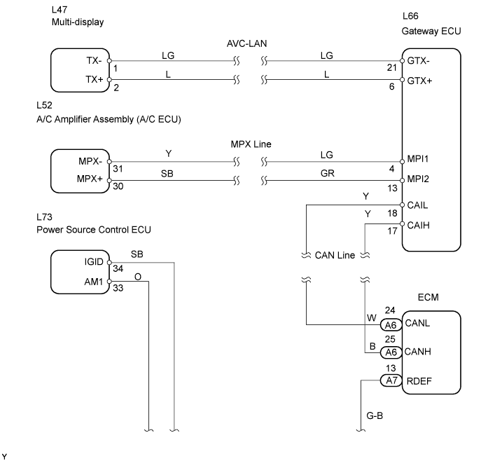
| 6.CHECK WIRE HARNESS (ENGINE ROOM NO. 1 RELAY BLOCK - ECM AND BATTERY) |
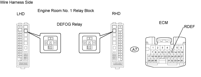
Remove the DEFOG relay from the engine room No. 1 relay block.
Disconnect the A7 ECM connector.
Measure the voltage of the wire harness side connectors.
| Tester Connection | Condition | Specified Condition |
| Relay block DEFOG relay terminal 1 - Body ground | Engine switch on (IG) | 10 to 14 V |
| R/B DEFOG relay terminal 5 - Body ground | Always | 10 to 14 V |
Measure the resistance of the wire harness side connectors.
| Tester Connection | Condition | Specified Condition |
| Relay block DEFOG relay terminal 2 - A7-13 (RDEF) | Always | Below 1 Ω |
|
| ||||
| OK | |
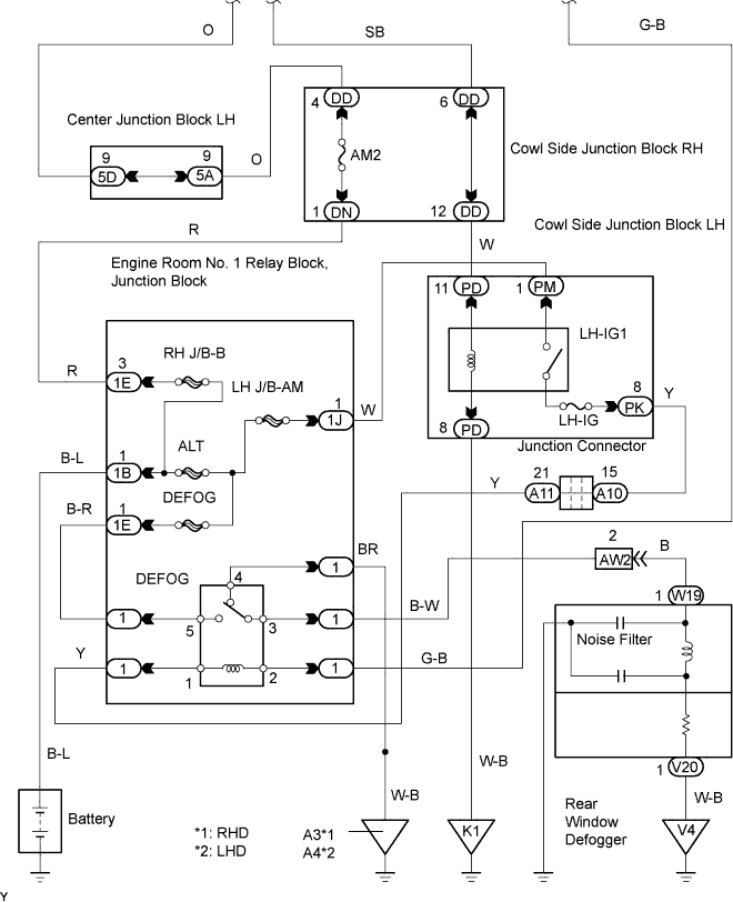
| 7.CHECK WIRE HARNESS (REAR WINDOW DEFOGGER - RELAY BLOCK AND BODY GROUND) |

Disconnect the W19 and V20 defogger connectors.
Disconnect the DEFOG relay from the engine room No.1 relay block.
Measure the resistance of the wire harness side connectors.
| Tester Connection | Specified Condition |
| W19-1 - Relay block DEFOG relay terminal 3 | Below 1 Ω |
| V20-1 - Body ground | Below 1 Ω |
| Relay block DEFOG relay terminal 4 - Body ground | Below 1 Ω |
|
| ||||
| OK | |
| 8.INSPECT REAR WINDOW DEFOGGER WIRE |
Turn the engine switch on (IG).
Turn the defogger switch ON.
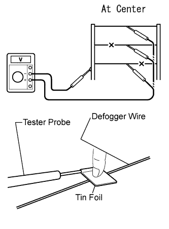 |
Check the voltage at the center of each defogger wire, as shown in the illustration.
| Voltage | Criteria |
| Approx. 5 V | Wire is not broken |
| Approx. 10 or 0 V | Wire is broken |
 |
Place the voltmeter's positive (+) lead against the defogger wire on the battery side.
Place the voltmeter's negative (-) lead with the foil strip against the wire on the ground side.
Slide the positive (+) lead from the battery side to the ground side.
The point where the voltage drops from approximately 10 V to 0 V is where the defogger wire is broken.
|
| ||||
| OK | |
| 9.CHECK OPERATION OF ECM WITH NEW OR NORMALLY FUNCTIONING ECM |
Temporarily replace the ECM with a new or normally functioning one.
Check that the malfunction disappears.
|
| ||||
| OK | ||
| ||
