DYNAMIC RADAR CRUISE CONTROL SYSTEM > INSTALLATION |
| 1. INSTALL MILLIMETER WAVE RADAR SENSOR ASSEMBLY |
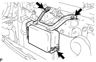 |
Install the sensor with the 3 bolts.
Connect the connector.
| 2. CONNECT CABLE TO NEGATIVE BATTERY TERMINAL |
| 3. ADJUST MILLIMETER WAVE RADAR SENSOR ASSEMBLY |
 |
Before adjusting the radar beam axis, prepare the vehicle as follows.
Check the tire pressure and adjust it if necessary.
Remove all excess weight from the vehicle (luggage, heavy objects, etc.).
w/ Air suspension:
Adjust the vehicle's height to the standard height.
Check and adjust the vertical direction of the radar sensor.
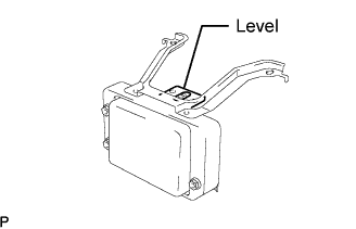 |
Remove dust, oil and foreign matter from the radar sensor's level rack.
Set a level on the radar sensor's level rack.
 |
Check that the level's air bubble is within the red frame.
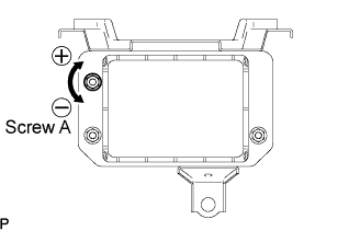
| Adjustment Direction | Adjustment Procedure | Adjustment Angle |
| Vertical adjustment |
| Approx. 1.0° per turn |
 |
Adjust the reflector height.
Adjust the reflector so that the center of the SST reflector is the same height as the millimeter wave radar sensor.
 |
Place the reflector.
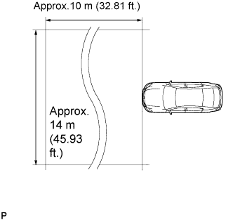
Hang the string (with weight) from the center of the vehicle rear's emblem. Mark the vehicle rear's center point on the ground. Repeat for the front of the vehicle.
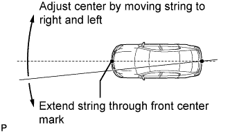 |
Set one end of the 10 m (32.82 ft.) string on the vehicle rear's center point. Run the string over the vehicle front's center point to a position 5 m (16.41 ft.) beyond the vehicle front's center point, as shown in the illustration. Mark the 5 m (16.41 ft.) position.
Using a tape measure, measure 12 mm (0.47 in.) to the left of the 5 m (16.41 ft.) position. Place the reflector at that position.

 |
Adjust the radar beam axis.
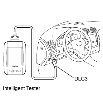
Connect the intelligent tester to the DLC3.
Turn the engine switch on (IG).
Turn the intelligent tester main switch ON, and turn the cruise control main switch ON.

Check and adjust the horizontal direction of the radar sensor.
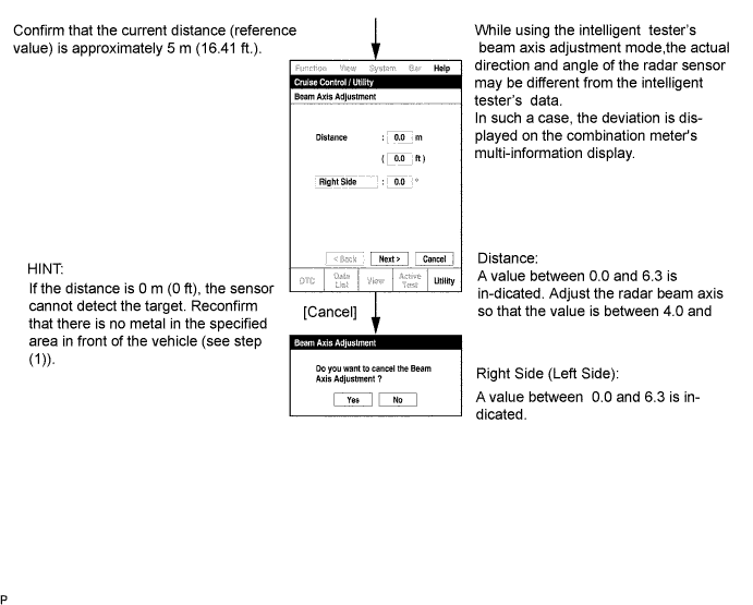
Check that the divergence of the radar beam axis is 0° .
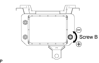 |
Based on the measured divergence of the beam axis, turn and adjust screw B for horizontal adjustment of the millimeter wave radar sensor using a hexagon wrench.
| Adjustment Direction | Adjustment Procedure | Adjustment Angle |
| Horizontal adjustment |
| Approx. 0.33° per turn |
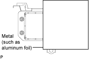 |
Reset the radar sensor's driving learning values. Prepare a type of metal that can block radio waves, such as aluminum foil. Cover the radar sensor's left half with the metal for 10 seconds.
Disconnect the intelligent tester from the DLC3.
Recheck and readjust the vertical direction of the radar sensor.
|
Set a level on the radar sensor's level rack.
|
Check that the level's air bubble is within the red frame.
| Adjustment Direction | Adjustment Procedure | Adjustment Angle |
| Vertical adjustment |
| Approx. 1.0° per turn |
| 4. INSTALL FRONT BUMPER COVER |
Connect the ultrasonic sensor connector.
 |
Attach the 3 claws on the LH side.
Attach the 3 claws on the RH side.
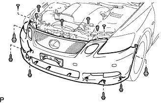 |
Install the bumper cover with the 2 clips, 6 screws and 5 bolts.
| 5. INSTALL FRONT FENDER LINER LH |
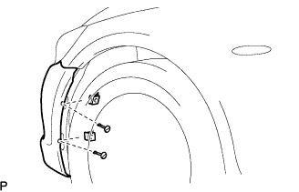 |
Install the fender liner with the 2 clips.
| 6. INSTALL FRONT FENDER LINER RH |
| 7. INSTALL ENGINE UNDER COVER |
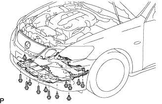 |
Install the under cover with the 3 clips and 10 screws.
| 8. INSTALL COOL AIR INTAKE DUCT SEAL |
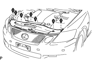 |
Install the duct seal with the 7 clips.
| 9. PERFORM INITIALIZATION |
Perform initialization (Click here).
