SFI SYSTEM > Cranking Holding Function Circuit |


| 1.CHECK OPERATION OF ENGINE CRANKING |
When turning the engine switch to start, check whether the starter motor starts.
|
| ||||
| NG | |
| 2.READ DATA LIST (STARTER SIGNAL) |
Connect the intelligent tester to the DLC3.
Enter the following menu: Powertrain / Engine / Data List / Primary / Starter Signal.
Confirm the starter signal status when the engine switch is operated.
| Engine Switch Position | Starter Signal |
| On (IG) | OFF |
| Start | ON |
|
| ||||
| NG | |
| 3.CHECK ECM (STSW AND STAR VOLTAGE) |
 |
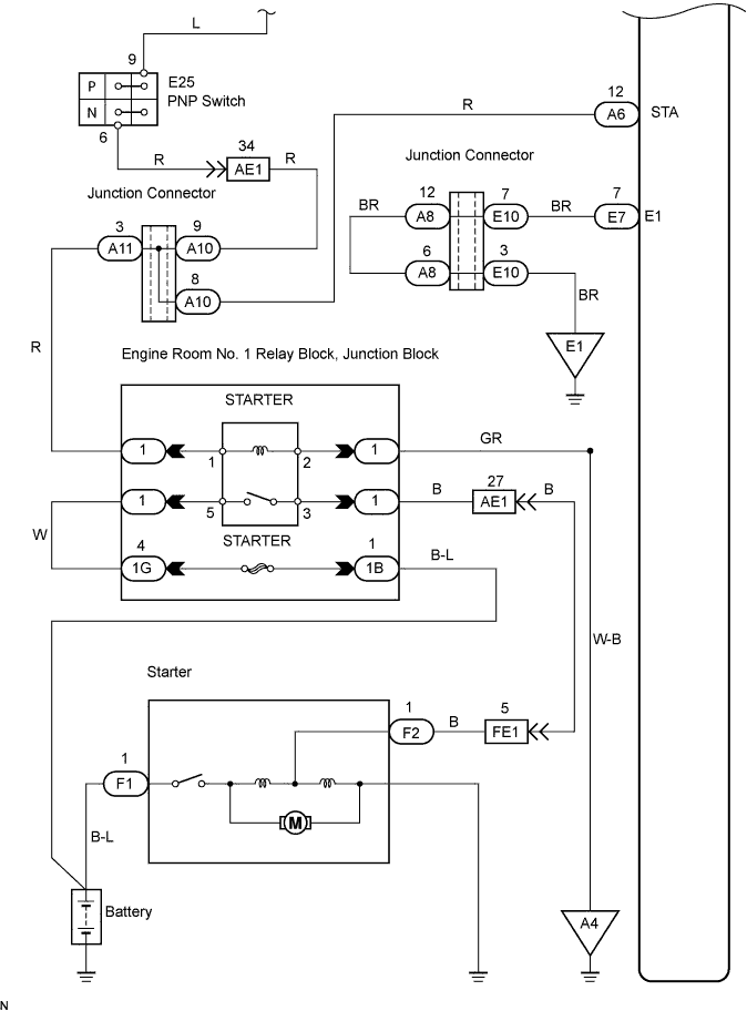
Measure the voltage of the A6 and E7 ECM connectors.
| Tester Connection | Specified Condition |
| A6-19 (STSW) - E7-7 (E1) | 9 to 14 V |
| E7-4 (STAR) - E7-7 (E1) | 9 to 14 V |
| Terminal STSW | Terminal STAR | Proceed to |
| 9 to 14 V | 9 to 14 V | A |
| 9 to 14 V | 0 V | B |
| 0 V | 0 V | C |
|
| ||||
|
| ||||
| A | |
| 4.INSPECT RELAY (Marking: ST CUT) |
 |
Remove the starter cut relay from engine room No. 2 relay block.
Measure the resistance of the relay.
| Tester Connection | Specified Condition |
| 3-5 | 10 kΩ or higher |
| 3-5 | Below 1 Ω (when battery voltage is applied to terminals 1 and 2) |
|
| ||||
| OK | |
| 5.INSPECT PARK / NEUTRAL POSITION SWITCH |
 |
Move the shift lever to the P or N position.
Disconnect the E25 PNP switch connector.
Measure the resistance of the PNP switch.
| Shift Position | Tester Connection | Specified Condition |
| P or N | 9 - 6 | Below 1 Ω |
|
| ||||
| OK | ||
| ||
| 6.INSPECT RELAY (Marking: STARTER) |
 |
Remove the starter relay from engine room No. 1 relay block.
Measure the resistance of the relay.
| Tester Connection | Specified Condition |
| 3 - 5 | 10 kΩ or higher |
| 3 - 5 | Below 1 Ω (when battery voltage is applied to terminals 1 and 2) |
|
| ||||
| OK | |
| 7.CHECK WIRE HARNESS (PARK / NEUTRAL POSITION SWITCH - STARTER RELAY) |
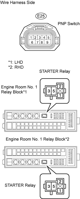 |
Check the wire harness between the PNP switch and starter relay.
Disconnect the E25 PNP switch connector.
Remove the starter relay from the engine room No. 1 relay block.
Measure the resistance of the wire harness side connectors.
| Tester Connection | Specified Condition |
| E25-6 (PNP switch) - Relay block STARTER relay terminal 1 | Below 1 Ω |
| E25-6 (PNP switch) - Relay block STARTER relay terminal 1 - Body ground | 10 kΩ or higher |
Check the wire harness between the starter relay and body ground.
Remove the starter relay from the engine room No. 1 relay block.
Measure the resistance of the wire harness side connector.
| Tester Connection | Specified Condition |
| Relay block STARTER relay terminal 2 - Body ground | Below 1 Ω |
|
| ||||
| OK | |
| 8.INSPECT ENGINE ROOM RELAY BLOCK (STARTER RELAY VOLTAGE) |
|
Remove the starter relay from the engine room No. 1 relay block.
Measure the resistance of the wire harness side connector.
| Tester Connection | Specified Condition |
| Relay block STARTER relay terminal 5 - Body ground | 9 to 14 V |
|
| ||||
| OK | |
| 9.INSPECT STARTER |
Inspect the starter (Click here).
|
| ||||
| OK | ||
| ||
| 10.CHECK WIRE HARNESS (ECM - POWER SOURCE CONTROL ECU) |
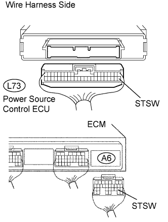 |
Disconnect the A6 ECM connector.
Disconnect the L73 ECU connector.
Measure the resistance of the wire harness side connectors.
| Tester Connection | Specified Condition |
| A6-19 (STSW) - L73-39 (STSW) | Below 1 Ω |
| A6-19 (STSW) or L73-39 (STSW) - Body ground | 10 kΩ or higher |
|
| ||||
| OK | ||
| ||
