ENGINE SWITCH > INSPECTION |
| 1. INSPECT ENGINE SWITCH |

| Tester Connection | Switch Position | Specified Condition |
| 7 (SS1) - 5 (GND) | Not pushed | 10 kΩ or higher |
| 2 (SS2) - 5 (GND) | Not pushed | 10 kΩ or higher |
| 7 (SS1) - 5 (GND) | Pushed | Below 1 Ω |
| 2 (SS2) - 5 (GND) | Pushed | Below 1 Ω |
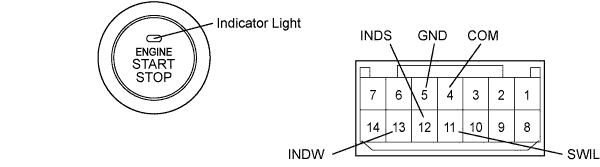
| Measurement Condition | Specified Condition |
| Battery positive (+) → Terminal 11 (SWIL) Battery negative (-) → Terminal 4 (COM) or 5 (GND) | Illuminates |
| Battery positive (+) → Terminal 12 (INDS) Battery negative (-) → Terminal 4 (COM) or 5 (GND) | Illuminates |
| Battery positive (+) → Terminal 13 (INDW) Battery negative (-) → Terminal 4 (COM) or 5 (GND) | Illuminates |
