FRONT WHEEL ALIGNMENT > ADJUSTMENT |
| 1. INSPECT TIRES |
| 2. MEASURE VEHICLE HEIGHT |
 |
Bounce the vehicle at the corners up and down to stabilize the suspension and inspect vehicle height.
| Front (A-B) | Rear (C) |
| 111 mm (4.37 in.) | 211 mm (8.31 in.) |
| Front (A-B) | Rear (C) |
| 113 mm (4.45 in.) | 208 mm (8.19 in.) |
| 3. INSPECT TOE-IN |
 |
Bounce the vehicle at the corners up and down to stabilize the suspension and inspect vehicle height.
| Toe-in (total) | A - B: 1+- 2 mm (0.04 +- 0.08 in.) |
| 4. ADJUST TOE-IN |
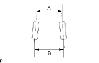
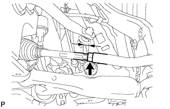
Measure the thread lengths of the right and left rack ends.
Remove the rack boot set clips.
Loosen the tie rod end lock nuts.
Adjust the rack ends if the difference in thread length between the right and left rack ends is not within the specified range.
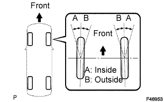
Extend the shorter rack end if the measured toe-in deviates toward the outer-side.
Shorten the longer rack end if the measured toe-in deviates toward the inner-side.
Turn the right and left rack ends by an equal amount to adjust toe-in.
 |
Make sure that the lengths of the right and left rack ends are the same.
Tighten the tie rod end lock nuts.
Place the boots on the seats and install the clips.
| 5. INSPECT WHEEL ANGLE |
 |
Turn the steering wheel fully left and right and measure the turning angle.
| Inside wheel | Outside wheel: Reference |
| 41°49' (41.82°) +- 2° | 36°11' (36.18°) |
| Inside wheel | Outside wheel: Reference |
| 41°48' (41.80°) +- 2° | 36°08' (36.13°) |
| 6. INSPECT CAMBER, CASTER AND STEERING AXIS INCLINATION |
Remove the center ornament.
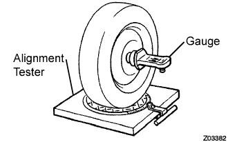 |
Put the front wheel on the center of the alignment tester.
Install the camber-caster-steering axis inclination gauge and attachment at the center of the axle hub or drive shaft.
Inspect the camber, caster and steering axis inclination.
| Camber | -0°23' +- 45' (-0.38° +- 0.75°) |
| Right-left error | 30' (0.5°) or less |
| Caster | 7°23' +- 45' (7.38° +- 0.75°) |
| Right-left error | 30' (0.5°) or less |
| Steering axis inclination | 9°23' +- 45' (9.38° +- 0.75°) |
| Right-left error | 30' (0.5°) or less |
| Camber | -0°26' +- 45' (-0.43° +- 0.75°) |
| Right-left error | 30' (0.5°) or less |
| Caster | 7°26' +- 45' (7.43° +- 0.75°) |
| Right-left error | 30' (0.5°) or less |
| Steering axis inclination | 9°26' +- 45' (9.43° +- 0.75°) |
| Right-left error | 30' (0.5°) or less |
Remove the camber-caster-steering axis inclination gauge and attachment.
Install the center ornament.
If the measured value is not within the specified range, inspect the suspension parts for damage and wear. Replace parts as necessary because camber, caster and steering axis inclination cannot be properly adjusted with any damage or worn parts.
| 7. INSPECT SUSPENSION PARTS |
 |
Inspect the front suspension member.
Measure the dimension between the center of the installation bolts of the front suspension lower arm assembly.
 |
Inspect the front suspension lower arm assembly.
Remove the front suspension lower arm assembly (Click here).
Measure the dimension between the center of the front suspension lower arm assembly bush and position A.
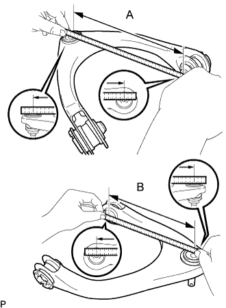 |
Inspect the front suspension upper arm assembly.
Remove the front suspension upper arm assembly (Click here).
Measure the dimension between the center of the front suspension upper arm assembly bush and the ball joint stud.
