FRONT SUSPENSION LOWER ARM > INSTALLATION

for Preparation Click here


1. INSTALL LOWER ARM NO.2 BRACKET SUB-ASSEMBLY
  1. Install the lower arm No.2 bracket sub-assembly.


    C104397E01
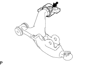
  1. Temporarily tighten the lower arm No.2 bracket sub-assembly to the front suspension lower arm with the nut and washer.


2. INSTALL FRONT LOWER BALL JOINT
  1. Install the front lower ball joint to the front suspension lower arm with the castle nut.

    Torque:
    162 N*m{ 1,650 kgf*cm , 120 ft.*lbf }

    NOTICE:
    Ensure that the thread and taper are free of oil, etc.

  1. Install a new clip to the front lower ball joint.

    NOTICE:
    Further tighten the nut up to 60° if the holes for the cotter pin are not aligned.


3. TEMPORARILY TIGHTEN FRONT SUSPENSION LOWER ARM


    C104396E02
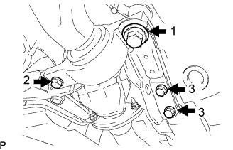
  1. Install the front suspension lower arm and side rail plate with the 4 bolts.

    Torque:
    Bolt 1:
    204 N*m{ 2,080 kgf*cm , 150 ft.*lbf }
    Bolt 2:
    86 N*m{ 877 kgf*cm , 63 ft.*lbf }
    Bolt 3:
    50 N*m{ 510 kgf*cm , 37 ft.*lbf }


    G033040
  1. Temporarily tighten the bolt, washer and nut.


    G033358
  1. Install the front lower ball joint with the 2 bolts.

    Torque:
    120 N*m{ 1,220 kgf*cm , 89 ft.*lbf }


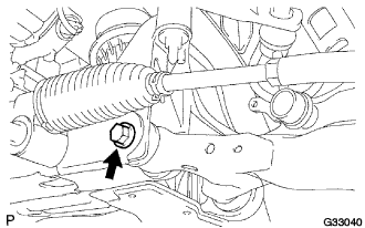
4. TEMPORARILY TIGHTEN FRONT SHOCK ABSORBER WITH COIL SPRING


    C104861E01
  1. Insert the bolt from the rear of the vehicle, and install the front shock absorber lower side on the front suspension lower arm. Temporarily tighten the nut while holding the bolt.


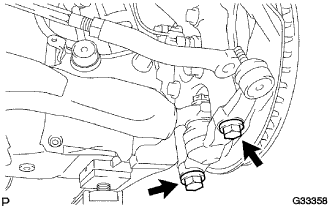
5. CONNECT FRONT STABILIZER LINK ASSEMBLY


    C104398E01
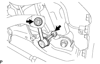
  1. Install the front stabilizer link assembly LH with the 2 nuts.

    Torque:
    84 N*m{ 856 kgf*cm , 62 ft.*lbf }

    HINT:
    If the ball joint turns together with the nut, use a hexagon (6 mm) wrench to hold the stud.


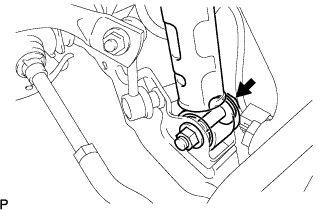
6. CONNECT TIE ROD ASSEMBLY
  1. Connect the tie rod end LH to the steering knuckle with the nut.

    Torque:
    65 N*m{ 663 kgf*cm , 50 ft.*lbf }

  1. Install a new clip.

    NOTICE:
    If the holes for the clip are not aligned, tighten the nut up to 60° further.


7. CONNECT SPEED SENSOR FRONT


    C105327
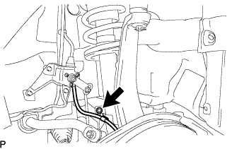
  1. Install the speed sensor front to the front shock absorber with coil spring with the bolt.

    Torque:
    6.0 N*m{ 61 kgf*cm , 53 in.*lbf }

    NOTICE:
    1. Do not twist the speed sensor front wire harness while installing.
    2. Be careful not to deform the bracket of the front shock absober with coil spring when installing the bolts.


8. CONNECT HEIGHT CONTROL SENSOR LINK SUB-ASSEMBLY FRONT


    C101053
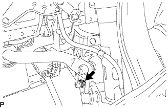
  1. Connect the height control sensor link sub-assembly front with the nut.

    Torque:
    5.4 N*m{ 55 kgf*cm , 48 in.*lbf }


9. STABILIZE SUSPENSION


    G033712
  1. Install the front wheel.

    Torque:
    103 N*m{ 1,050 kgf*cm , 76 ft.*lbf }

  1. Lower the vehicle and bounce it up and down several times to stabilize the front suspension.

  1. Remove the front wheel.

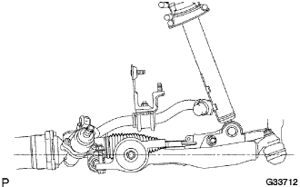
  1. Jack up the front suspension lower arm placing a wooden block in between. Apply a load to the front suspension so that the front suspension lower arm is placed in a horizontal position.


10. FULLY TIGHTEN FRONT SHOCK ABSORBER WITH COIL SPRING


    C104861E01
  1. Fully tighten the bolt on the lower side of the front shock absorber while holding the nut.

    Torque:
    157 N*m{ 1,600 kgf*cm , 116 ft.*lbf }


11. FULLY TIGHTEN FRONT SUSPENSION LOWER ARM


    G033040
  1. Fully tighten the bolt on the front of the front suspension lower arm.

    Torque:
    135 N*m{ 1,380 kgf*cm , 100 ft.*lbf }


    C104536
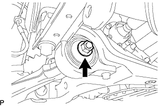
  1. Fully tighten the installation nut of the lower arm No.2 bracket sub-assembly.

    Torque:
    113 N*m{ 1,150 kgf*cm , 83 ft.*lbf }


12. INSTALL ENGINE UNDER COVER


13. INSTALL FRONT WHEEL

Torque:
103 N*m{ 1,050 kgf*cm , 76 ft.*lbf }


14. HEADLIGHT AIMING INSPECTION
  1. Cover or disconnect the connector of the headlight on the opposite side to prevent light from the head-light not being inspected from affecting the headlight aiming inspection.

    NOTICE:
    Do not keep the headlight covered for more than 3 minutes. The headlight lens is made of synthetic resin, and may easily melt or be damaged due to heat.

    HINT:
    When checking the aim of the high-beam, cover the low-beam or disconnect the connector.

  1. Start the engine.

    NOTICE:
    Engine rpm must be 1,500 or more.

  1. w/ headlight leveling switch:
    Set the headlight leveling switch to 0 (zero).


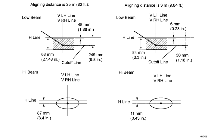
  1. Turn on the headlight and make sure that the cutoff line falls within the specified area, as shown in the illustration.


    I041709E01

    HINT:
    1. Alignment distance is 25 m (82 ft.):
      The cutoff line is 48 mm (1.88 in.) to 698 mm (27.48 in.) below the H line with low-beam.
    2. Alignment distance is 3 m (9.84 ft.):
      The cutoff line is 6 mm (0.23 in.) to 84 mm (3.3 in.) below the H line with low-beam.
    3. Alignment distance is 25 m (82 ft.):
      The cutoff line is 249 mm (9.8 in.) below the H line with low-beam.
    4. Alignment distance is 3 m (9.84 ft.):
      The cutoff line is 30 mm (1.88 in.) below the H line with low-beam.
    5. Since the low-beam light and the high-beam light are a unit, if the aim of either one is correct, the other should also be correct. However, check both beams just to make sure.


15. HEADLIGHT AIMING ADJUSTMENT


    E109374E01
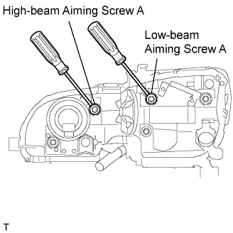
  1. Adjust the aim vertically:
    Adjust the headlight aim into the specified range by turning aiming screw A with a screwdriver.

    NOTICE:
    The final turn of the aiming screw should be made in the clockwise direction. If the screw is tightened excessively, loosen and then retighten it so that the final turn of the screw is in the clockwise direction.

    HINT:
    1. Perform the low-beam aim adjustment.
    2. The headlight aim moves up when turning the aiming screw clockwise, and moves down when turning the aiming screw counterclockwise.


    E109373E02
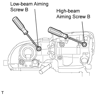
  1. Adjust the aim horizontally:
    Adjust the headlight aim into the specified range by turning aiming screw B with a screwdriver.

    NOTICE:
    The final turn of the aiming screw should be made in the clockwise direction. If the screw is tightened excessively, loosen and then retighten it, so that the final turn of the screw is in the clockwise direction.

    HINT:
    1. Perform the low-beam aim adjustment.


16. INSPECT VEHICLE STABILITY CONTROL SYSTEM
(Click here)


17. INSPECT AND ADJUST FRONT WHEEL ALIGNMENT
(Click here)