REAR WHEEL ALIGNMENT > ADJUSTMENT

for Preparation Click here


1. INSPECT TIRES
(Click here)


2. MEASURE VEHICLE HEIGHT
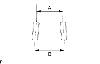
(Click here)

NOTICE:
Before inspecting wheel alignment, adjust vehicle height to the specified value.


3. INSPECT TOE-IN


    C107735E01
  1. Bounce the vehicle at the corners up and down to stabilize the suspension and inspect vehicle height.

    Toe-in:
    Toe-in
    (total)
    A - B: 3 +- 2 mm (0.12 +- 0.08 in.)

    If the toe-in is not within the specified range, inspect the suspension parts and replace if necessary.


4. ADJUST TOE-IN


    G033372
  1. Loosen the toe adjust cam nut.

  1. Turn the adjust cams by an equal amount to adjust toe-in.

    HINT:
    1. Try to adjust the toe-in to the center value.
    2. The toe-in will change by the following specifications corresponding to each graduation of the cam.
      Approx. 4.0 mm (0.16 in.)

  1. Tighten the nut.

    Torque:
    50 N*m{ 510 kgf*cm , 37 ft.*lbf }


5. INSPECT CAMBER


    C107736E01
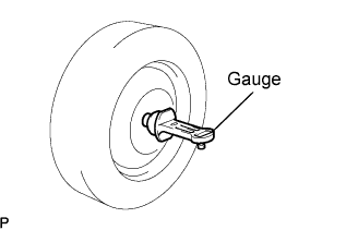
  1. Install a camber-caster-kingpin gauge or put the wheels on a wheel alignment tester.

  1. Inspect the camber.

    CAMBER:
    3GR-FSE 3GR-FE:
    Camber
    -1°10' +- 45'
    (-1.17° +- 0.75°)
    Right-left error
    30' (0.5°) or less
    3UZ-FE:
    Camber
    -1°19' +- 45'
    (-1.32° +- 0.75°)
    Right-left error
    30' (0.5°) or less

    If the measured value is not within the specified range, inspect the suspension parts for damage and wear. Replace parts as necessary because camber cannot be properly adjusted with any damaged or worn parts.


6. INSPECT SUSPENSION PARTS


    G031255
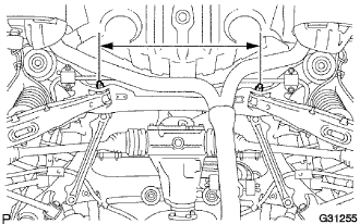
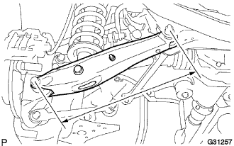
  1. Inspect the rear suspension member.

    1. Measure the distance between the centers of the installation bolts of the rear suspension arm assembly No.2 LH and RH.

      Standard:
      536.8 to 543.7 mm (21.13 to 21.41 in.)

      HINT:
      If the distance is not within the specified range, replace the rear suspension member.


    2. C104402
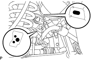
    3. Visually inspect the press holes on the installation area of the upper control arm assembly rear No.2.

      Standard:
      The hole are not deformed.

      HINT:
      If the holes are deformed, replace the rear suspension member.


    G031257
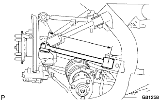
  1. Inspect the rear suspension arm assembly No.2.

    1. Remove the rear wheel.

    2. Measure the distance between the centers of the 2 installation bolts of the rear suspension arm assembly No.2.

      Standard:
      433.5 to 434.5 mm (17.07 to 17.11 in.)

      HINT:
      If the distance is not within the specified range, replace the rear suspension arm assembly No.2.

    3. Install the rear wheel.

      Torque:
      103 N*m{ 1,050 kgf*cm , 76 ft.*lbf }


    G031258
  1. Inspect the upper control arm assembly rear No.2.

    1. Measure the distance between the centers of the installation bolt of the upper control arm assembly rear No.2 and the ball joint stud.

      Standard:
      307.3 to 308.7 mm (12.10 to 12.15 in.)

      HINT:
      If the distance is not within the specified range, replace the upper control arm assembly rear No.2.