DTC B1263 Luggage Room Junction Block ECU Communication Stop |
| DTC No. | DTC Detection Condition | Trouble Area |
| B1263 | No.1 junction block assembly (multiplex network rear ECU) communication stops |
|

| 1.INSPECT FUSE (MPX-B, D/C CUT) |
Remove the MPX-B and D/C CUT fuses from the engine room No. 1 relay block.
Measure the resistance of the fuses.
|
| ||||
| OK | |
| 2.CHECK WIRE HARNESS (NO. 1 JUNCTION BLOCK ASSEMBLY - BATTERY AND BODY GROUND) |
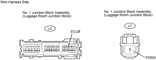
Disconnect the LC and LF junction block connectors.
Measure the resistance and voltage of the wire harness side connectors.
| Tester Connection | Specified Condition |
| LC-15 (ECUB) - Body ground | 10 to 14 V |
| Tester Connection | Specified Condition |
| LF-1 (PGND) - Body ground | Below 1 Ω |
|
| ||||
| OK | |
| 3.CHECK RESISTANCE OF COMMUNICATION LINE |

Disconnect the L66 connector.
Disconnect the V3 and LC junction block connectors.
Measure the resistance of the wire harness side connectors.
| Tester Connection | Specified Condition |
| LC-21 (MPX1) - L66-5 (MPL1) | Below 1 Ω |
| LC-31 (MPX2) - W3-15 (MPX1) | Below 1 Ω |
| Result | Proceed to |
| Both are OK | A |
| One is OK | B |
| Both are NG | C |
|
| ||||
|
| ||||
| A | ||
| ||
