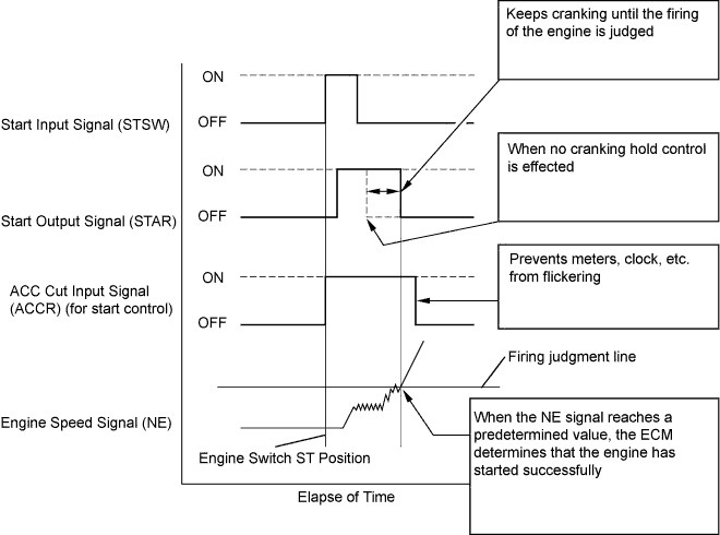
SFI SYSTEM > Cranking Holding Function Circuit |
| 1.CHECK OPERATION OF ENGINE CRANKING |
When turning the engine switch to the START position, check whether the starter motor starts.
|
| ||||
| NG | |
| 2.READ VALUE OF INTELLIGENT TESTER (STA SIGNAL) |
Connect the intelligent tester to the DLC3.
Turn the engine switch on (IG) and turn the tester ON.
Enter the following menus: Power train / Engine / Data List / Starter Signal.
Check the result when the engine switch is turned to on (IG) and START.
| Engine Switch Position | ON (IG) | START |
| Starter Signal | OFF | ON |
|
| ||||
| NG | |
| 3.INSPECT ECM (STAR AND STSW VOLTAGE) |
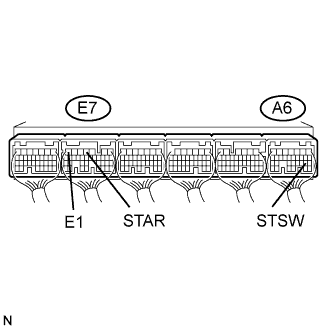 |
Measure the voltage between the terminals of the A6 and E7 ECM connectors, while cranking the engine.
| Tester Connection | Specified Condition |
| STAR (E7-4) - E1 (E7-7) | 9 to 14 V |
| STSW (A6-19) - E1 (E7-7) | 9 to 14 V |
| Terminal STAR | Terminal STSW | Proceed to |
| 9 to 14 V | 9 to 14 V | A |
| 0 V | 9 to 14 V | B |
| 0 V | 0 V | C |
|
| ||||
|
| ||||
| A | |
| 4.INSPECT ST CUT RELAY |
 |
Remove the ST CUT relay from the engine room No. 2 relay block
Measure the resistance of the ST CUT relay.
| Tester Connection | Specified Condition |
| 3 - 5 | 10 kΩ or higher |
| 3 - 5 | Below 1 Ω (when battery voltage applied to terminals 1 and 2) |
|
| ||||
| OK | |
| 5.INSPECT PARK/NEUTRAL POSITION SWITCH ASSEMBLY |
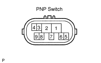 |
Disconnect the E25 park/neutral position (PNP) switch connector.
Measure the resistance between each terminal shown below when the shift lever is moved to each range.
| Shift Position | Tester Connection | Specified Condition |
| P | 4 - 5 | Below 1 Ω |
| N | 4 - 5 | Below 1 Ω |
|
| ||||
| OK | ||
| ||
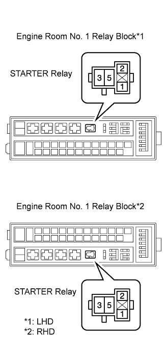
| 6.INSPECT STARTER RELAY |
|
Remove the STARTER relay from the engine room No. 1 relay block.
Measure the resistance of the STARTER relay.
| Tester Connection | Specified Condition |
| 3 - 5 | 10 kΩ or higher |
| 3 - 5 | Below 1 Ω (when battery voltage applied to terminals 1 and 2) |
|
| ||||
| OK | |
| 7.CHECK HARNESS AND CONNECTOR (PARK/NEUTRAL POSITION SWITCH - STARTER RELAY) |
 |
Check the harness and the connectors between the park/neutral position switch and the STARTER relay.
Disconnect the E25 position switch connector.
Remove the STARTER relay from the engine room No. 1 relay block
Measure the resistance of the wire harness side connectors.
| Tester Connection | Specified Condition |
| Park/Neutral position switch (E25-5) - STARTER relay (1) | Below 1 Ω |
| Tester Connection | Specified Condition |
| Park/Neutral position switch (E25-5) or STARTER relay (1) - Body ground | 10 kΩ or higher |
Check the harness and the connector between the STARTER relay and the body ground.
Remove the STARTER relay from the engine room No. 1 relay block.
Measure the resistance of the STARTER relay and the body ground.
| Tester Connection | Specified Condition |
| STARTER relay (2) - Body ground | Below 1 Ω |
|
| ||||
| OK | |
| 8.INSPECT ENGINE ROOM RELAY BLOCK (STARTER RELAY VOLTAGE) |
 |
Remove the STARTER relay from the engine room No. 1 relay block.
Measure the voltage between the terminals of the engine room No. 1 relay block and the body ground.
| Tester Connections | Specified Condition |
| STARTER relay (5) - Body ground | 9 to 14 V |
|
| ||||
| OK | |
| 9.INSPECT STARTER ASSEMBLY |
|
| ||||
| OK | ||
| ||
| 10.CHECK HARNESS AND CONNECTOR (POWER SOURCE CONTROL ECU - ECM) |
 |
Check the harness and the connectors between the power source control ECU and ECM.
Disconnect the L73 power source control ECU connector.
Disconnect the A6 ECM connector.
Measure the resistance of the wire harness side connectors.
| Tester Connection | Specified Condition |
| STSW (L73-39) - STSW (A6-19) | Below 1 Ω |
| Tester Connection | Specified Condition |
| STSW (L73-39) or STSW (A6-19) - Body ground | 10 kΩ or higher |
|
| ||||
| OK | ||
| ||
