DTC    B1214    Door System Communication Bus Malfunction (+B Short)

DTC    B1215    Door System Communication Bus Malfunction (GND Short)

for Preparation Click here


DESCRIPTION

  1. When a +B or body ground short circuit is detected on the door system communication bus (BEAN), the door system communication bus (BEAN) is disabled and a DTC is output.

DTC No.
DTC Detection Condition
Trouble Area
B1214
Door system communication circuit and +B battery system short
  1. Power source control ECU
  2. Sliding roof drive gear sub-assembly (sliding roof control ECU)
  3. Multiplex network door ECU front RH (front door ECU RH)
  4. Multiplex network door ECU rear RH (rear door RH ECU)
  5. Multiplex network switch (rear RH)
  6. Multiplex network door ECU rear LH (rear door LH ECU)
  7. Multiplex network switch (rear LH)
  8. Multiplex network door ECU front LH (front door ECU LH)
  9. Multiplex network master switch
  10. Sliding roof control ECU
  11. Overhead junction block
  12. Wire harness
B1215
Door system communication circuit and body ground short
  1. Power source control ECU
  2. Sliding roof drive gear sub-assembly (sliding roof control ECU)
  3. Multiplex network door ECU front RH (front door ECU RH)
  4. Multiplex network door ECU rear RH (rear door RH ECU)
  5. Multiplex network switch (rear RH)
  6. Multiplex network door ECU rear LH (rear door LH ECU)
  7. Multiplex network switch (rear LH)
  8. Multiplex network door ECU front LH (front door ECU LH)
  9. Multiplex network master switch
  10. Sliding roof control ECU
  11. Overhead junction block
  12. Wire harness

WIRING DIAGRAM


B111300E01


INSPECTION PROCEDURE

1.CHECK DIAGNOSTIC TROUBLE CODE (A ECU)

B079627E02

  1. Disconnect the A ECU connector and check for DTCs B1214 and B1215.

    OK:
    DTCs B1214 and B1215 are not output.

    NOTICE:
    Reconnect the connector before starting the next check.

    HINT:
    1. The A ECU in the door system bus represents the power source control ECU.
    1. If the result is as specified, the disconnected A ECU (power source control ECU) is malfunctioning.


NG
Go to step 2
OK

REPLACE A ECU 

2.CHECK DIAGNOSTIC TROUBLE CODE (B ECU)

B079628E03

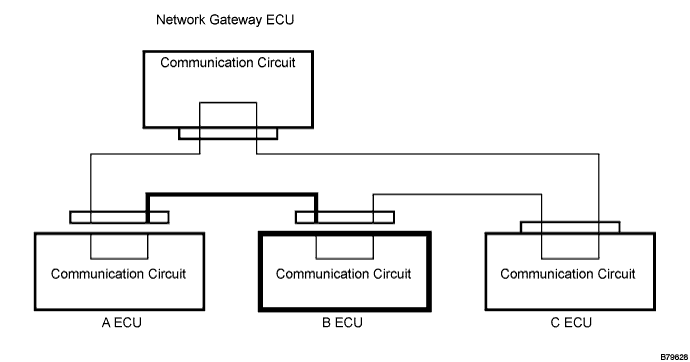
  1. Disconnect the A ECU and B ECU connectors and check for DTCs B1214 and B1215.

    OK:
    DTCs B1214 and B1215 are not output.

    NOTICE:
    Disconnect the connectors one by one. Reconnect the connectors before starting the next check.

    HINT:
    1. The B ECU in the door system bus represents one of the following: position control ECU, multiplex network door ECU front RH (front door ECU RH), multiplex network door ECU rear RH (rear door RH ECU), multiplex network switch (rear RH), multiplex network door ECU rear LH (rear door LH ECU), multiplex network switch (rear LH), multiplex network door ECU front LH (front door ECU LH), multiplex network master switch, sliding roof control ECU or overhead junction block.
    1. If the result is as specified, the disconnected B ECU (one of the ECUs from the above list) or the wire harness between the A ECU and B ECU is malfunctioning.


NG
Go to step 4
OK


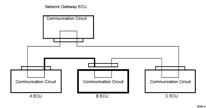
3.CHECK WIRE HARNESS BETWEEN A ECU AND B ECU

B079912E02

  1. Disconnect the B ECU connector and check for DTCs B1214 and B1215.

    OK:
    DTCs B1214 and B1215 are not output.

    NOTICE:
    Reconnect the connector before starting the next check.

    HINT:
    If the result is as specified, the wire harness between the A ECU and B ECU is functioning normally but the disconnected B ECU is malfunctioning.


NG
REPAIR OR REPLACE WIRE HARNESS BETWEEN A ECU AND B ECU
OK

REPLACE B ECU 

4.CHECK DIAGNOSTIC TROUBLE CODE (C ECU)

B079630E02

  1. Disconnect the B ECU and C ECU connectors and check for DTCs B1214 and B1215.

    OK:
    DTCs B1214 and B1215 are not output.

    NOTICE:
    Disconnect the connectors one by one. Reconnect the connectors before starting the next check.

    HINT:
    1. The C ECU in the door system bus represents the power source control ECU.
    1. If the result is as specified, the disconnected C ECU (power source control ECU) or the wire harness between the B ECU and C ECU is malfunctioning.


NG
Go to step 6
OK


5.CHECK WIRE HARNESS BETWEEN B ECU AND C ECU

B079631E02

  1. Disconnect the C ECU connector and check for DTCs B1214 and B1215.

    OK:
    DTCs B1214 and B1215 are not output.

    NOTICE:
    Reconnect the connector before starting the next check.

    HINT:
    If the result is as specified, the wire harness between the B ECU and C ECU is functioning normally but the disconnected C ECU is malfunctioning.


NG
REPAIR OR REPLACE WIRE HARNESS BETWEEN B ECU AND C ECU
OK

REPLACE C ECU 

6.CHECK WIRE HARNESS BETWEEN NETWORK GATEWAY ECU AND A ECU OR C ECU

B079632E02

  1. Check for a short-circuit in B+ or body ground.

    1. Disconnect the A ECU, C ECU and gateway ECU connectors.

    2. Measure the voltage and resistance of the wire harness side connectors.


Standard voltage:

Tester Connection
Specified Condition
A ECU connector / Network gateway ECU connector - Body ground
Below 1 V
C ECU connector / Network gateway ECU connector - Body ground
Below 1 V


Standard resistance:

Tester Connection
Specified Condition
A ECU connector / Network gateway ECU connector - Body ground
10 kΩ or higher
C ECU connector / Network gateway ECU connector - Body ground
10 kΩ or higher

HINT:
  1. The A ECU in the door system bus represents the certification ECU.
  1. The C ECU in the door system bus represents the power source control ECU.


NG
REPAIR OR REPLACE WIRE HARNESS BETWEEN NETWORK GATEWAY ECU AND A ECU OR C ECU
OK

REPLACE NETWORK GATEWAY ECU