FRONT ACCELERATION SENSOR > REPLACEMENT |
| 1. DISCONNECT CABLE FROM NEGATIVE BATTERY TERMINAL |
| 2. REMOVE FRONT DOOR SCUFF PLATE LH |
 |
Using a moulding remover, detach the 5 claws and remove the scuff plate.
| 3. REMOVE FRONT DOOR OPENING TRIM COVER LH |
Using a moulding remover, detach the 3 claws and remove the trim cover.
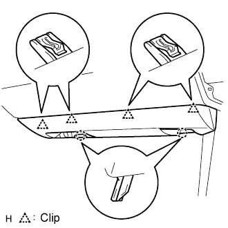
| 4. REMOVE INSTRUMENT SIDE PANEL LH (for RHD) |
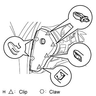 |
Using a screwdriver, detach the 2 claws and 4 clips, and remove the side panel.
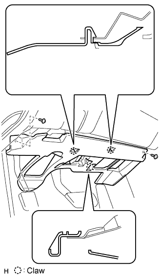
| 5. REMOVE INSTRUMENT PANEL UNDER COVER SUB-ASSEMBLY NO.1 (for LHD) |
 |
Remove the 2 screws.
Detach the 2 claws.
Remove the under cover and then disconnect the connector.
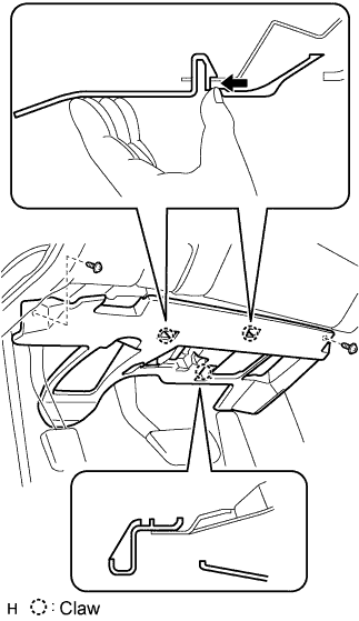
| 6. REMOVE INSTRUMENT PANEL UNDER COVER SUB-ASSEMBLY NO.2 (for RHD) |
 |
Using a screwdriver, detach the 4 clips.
Disconnect the connector and clamp, and remove the under cover.
| 7. REMOVE INSTRUMENT PANEL AIRBAG ASSEMBLY LOWER NO.2 (for RHD) |
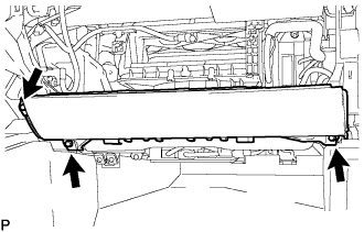 |
Remove the 3 bolts and front passenger side knee airbag assembly.
Disconnect the connector.
| 8. REMOVE GLOVE COMPARTMENT DOOR ASSEMBLY (for RHD) |
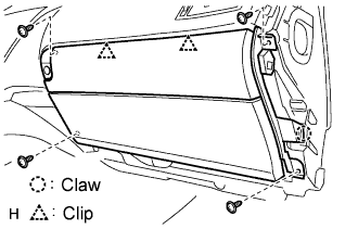 |
Remove the 4 screws.
Detach the 2 clips and claw.
Disconnect the connector and clamp.
Remove the glove compartment door.
| 9. REMOVE ACCELERATION SENSOR ASSEMBLY (for LHD) |
Disconnect the acceleration sensor connector.
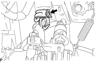 |
Remove the nut and the acceleration sensor assembly.
| 10. REMOVE ACCELERATION SENSOR ASSEMBLY (for RHD) |
Disconnect the acceleration sensor connector.
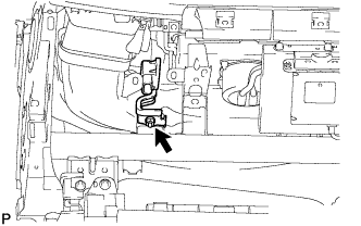 |
Remove the nut and the acceleration sensor assembly.
| 11. REMOVE ACCELERATION SENSOR (for LHD) |
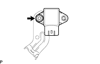 |
Remove the nut and the acceleration sensor from the bracket.
| 12. REMOVE ACCELERATION SENSOR (for RHD) |
 |
Remove the nut and the acceleration sensor from the bracket.
| 13. INSTALL ACCELERATION SENSOR (for LHD) |
|
Install the acceleration sensor to the bracket with the nut.
| 14. INSTALL ACCELERATION SENSOR (for RHD) |
|
Install the acceleration sensor to the bracket with the nut.
| 15. INSTALL ACCELERATION SENSOR ASSEMBLY (for LHD) |
|
Install the acceleration sensor assembly with the nut.
| 16. INSTALL ACCELERATION SENSOR ASSEMBLY (for RHD) |
|
Install the acceleration sensor assembly with the nut.
| 17. INSTALL GLOVE COMPARTMENT DOOR ASSEMBLY (for RHD) |
 |
Attach the 2 clips and claw to install the glove compartment door.
Connect the connector and clamp.
Install the 4 screws.
| 18. INSTALL INSTRUMENT PANEL AIRBAG ASSEMBLY LOWER NO.2 (for RHD) |
|
Connect the connector.
Install the front passenger side knee airbag assembly with the 3 bolts.
| 19. INSTALL INSTRUMENT PANEL UNDER COVER SUB-ASSEMBLY NO.1 (for LHD) |
 |
Connect the connectors.
Attach the 2 claws to install the under cover.
Install the 2 screws.
| 20. INSTALL INSTRUMENT PANEL UNDER COVER SUB-ASSEMBLY NO.2 (for RHD) |
 |
Connect the connector and clamp.
Attach the 4 clips to install the under cover.
| 21. INSTALL INSTRUMENT SIDE PANEL LH (for RHD) |
 |
Attach the 2 claws and 4 clips to install the side panel.
| 22. INSTALL FRONT DOOR OPENING TRIM COVER LH |
| 23. INSTALL FRONT DOOR SCUFF PLATE LH |
 |
Attach the 5 claws to install the scuff plate.
Pull out the folded lip of the weatherstrip.
| 24. CONNECT CABLE TO NEGATIVE BATTERY TERMINAL |
| 25. INSPECT SRS WARNING LIGHT (for RHD) |
| 26. INSPECT ADAPTIVE VARIABLE SUSPENSION SYSTEM |
| 27. PERFORM INITIALIZATION |
Some systems need initialization when disconnecting the cable from the negative battery terminal (Click here).
