ABSORBER CONTROL ECU > REPLACEMENT |
| 1. DISCONNECT CABLE FROM NEGATIVE BATTERY TERMINAL |
| 2. REMOVE FRONT DOOR SCUFF PLATE RH |
| 3. REMOVE INSTRUMENT PANEL UNDER COVER SUB-ASSEMBLY NO.2 (for LHD) |
 |
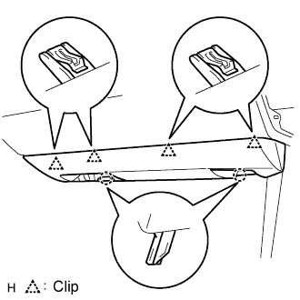
Using a screwdriver, detach the 4 clips.
Disconnect the connector and clamp, and remove the under cover.
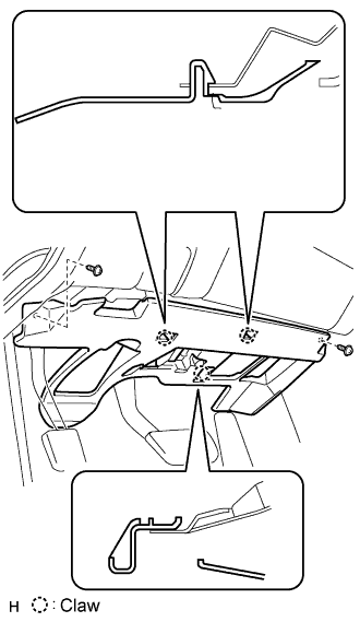
| 4. REMOVE INSTRUMENT PANEL UNDER COVER SUB-ASSEMBLY NO.1 (for RHD) |
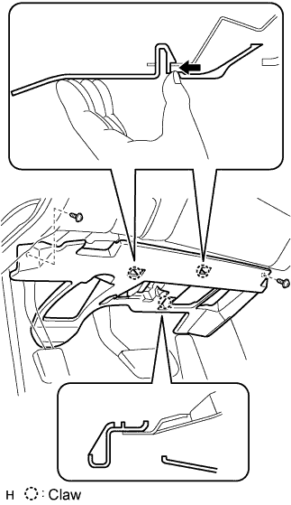 |
Remove the 2 screws.
Detach the 2 claws.
Remove the under cover and then disconnect the connector.
| 5. REMOVE ABSORBER CONTROL ECU |
Turn back the floor carpet to remove the absorber control ECU.
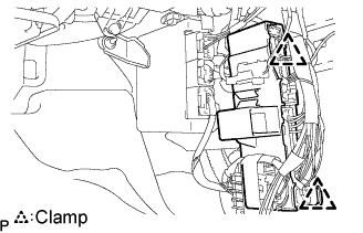 |
Disengage the 2 clamps to remove the wire harness from the vehicle body.
Disconnect the connectors from the absorber control ECU.
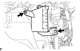 |
Remove the bolt, nut and the absorber control ECU.
| 6. INSTALL ABSORBER CONTROL ECU |
|
Install the absorber control ECU with the bolt and nut.
Connect the connectors to the absorber control ECU.
|
Engage the 2 clamps to install the wire harness to the vehicle body.
Install the floor carpet.
| 7. INSTALL INSTRUMENT PANEL UNDER COVER SUB-ASSEMBLY NO.2 (for LHD) |
 |
Connect the connector and clamp.
Attach the 4 clips to install the under cover.
| 8. INSTALL INSTRUMENT PANEL UNDER COVER SUB-ASSEMBLY NO.1 (for RHD) |
 |
Connect the connectors.
Attach the 2 claws to install the under cover.
Install the 2 screws.
| 9. REMOVE FRONT DOOR SCUFF PLATE RH |
| 10. CONNECT CABLE TO NEGATIVE BATTERY TERMINAL |
| 11. INSPECT ADAPTIVE VARIABLE SUSPENSION SYSTEM |
| 12. PERFORM INITIALIZATION |
