DTC B2272 Ignition 1 Monitor Malfunction |
| DTC No. | DTC Detection Condition | Trouble Area |
| B2272 | IG1 relay actuation circuit inside power source control ECU or other related circuit is malfunctioning |
|
| 1.CHECK WIRE HARNESS (COWL SIDE JUNCTION BLOCK RH - ECU AND BODY GROUND) |
 |
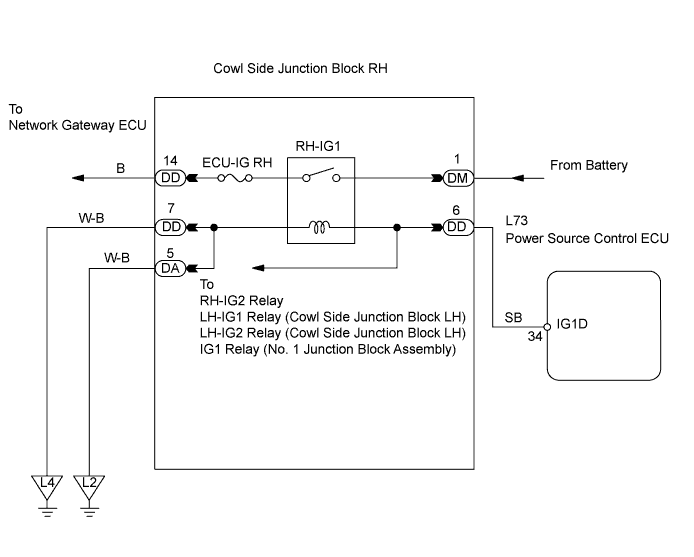
Disconnect the DA and DD junction block connectors.
Disconnect the L73 ECU connector.
Measure the resistance of the wire harness side connectors.
| Tester Connection | Specified Condition |
| DD-6 - L73-34 (IG1D) | Below 1 Ω |
| DA-5 or DD-7 - Body ground | Below 1 Ω |
| DD-6 or L73-34 (IG1D) - Body ground | 10 kΩ or higher |
|
| ||||
| OK | |
| 2.CHECK COWL SIDE JUNCTION BLOCK RH (RH-IG1 RELAY) |
 |
Disconnect the DD and DM junction block connectors.
Measure the resistance of the junction block connectors.
| Tester Connection | Condition | Specified Condition |
| DM-1 - DD-14 | When battery voltage is not applied to terminals DD-6 and DA-5 or DD-7 | 10 kΩ or higher |
| DM-1 - DD-14 | When battery voltage is applied to terminals DD-6 and DA-5 or DD-7 | Below 1 Ω |
|
| ||||
| OK | ||
| ||
