DTC B2284 Brake Signal Malfunction (Cable-Information does not Match to Bean-Information) |
| DTC No. | DTC Detection Condition | Trouble Area |
| B2284 | Communication or communication line is abnormal between power source control ECU and stop light switch |
|
| 1.READ VALUE OF INTELLIGENT TESTER (STOP LIGHT SWITCH) |
Check the Data List for proper functioning of the stop light switch.
| Item | Measurement Item/Display (Range) | Normal Condition | Diagnostic Note |
| Stop Lamp SW1 | Stop light switch 1/ ON or OFF | ON: Brake pedal depressed OFF: Brake pedal released | - |
|
| ||||
| OK | ||
| ||
| 2.INSPECT FUSE (STOP SW) |
Remove the STOP SW fuse from cowl side junction block RH.
Measure the resistance of the fuse.
|
| ||||
| OK | |
| 3.INSPECT STOP LIGHT SWITCH |
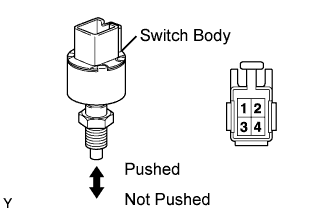 |
Remove the switch.
Measure the resistance of the switch.
| Tester Connection | Condition | Specified Condition |
| 1 - 2 | Switch pin not pushed | Below 1 Ω |
| 3 - 4 | Switch pin not pushed | 10 kΩ or higher |
| 1 - 2 | Switch pin pushed | 10 kΩ or higher |
| 3 - 4 | Switch pin pushed | Below 1 Ω |
|
| ||||
| OK | |
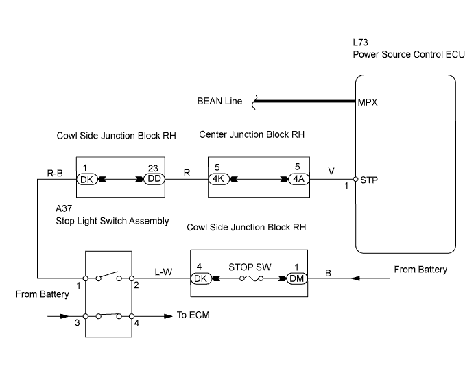
| 4.CHECK WIRE HARNESS (STOP LIGHT SWITCH - POWER SOURCE CONTROL ECU AND BATTERY) |
 |
Disconnect the A37 switch connector.
Disconnect the L73 ECU connector.
Measure the voltage and resistance of the wire harness side connectors.
| Tester Connection | Specified Condition |
| A37-2 - Body ground | 10 to 14 V |
| Tester Connection | Specified Condition |
| A37-1 - L73-1 (STP) | Below 1 Ω |
| A37-1 or L73-1 (STP) - Body ground | 10 kΩ or higher |
|
| ||||
| OK | |
| 5.CHECK POWER SOURCE CONTROL ECU |
Temporarily replace the power source control ECU with a new or normally functioning one.
Check that the engine starts normally.
|
| ||||
| OK | ||
| ||
