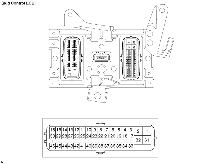
Symbols (Terminal No.)
| Terminal Description
|
GND (1)
| Skid control ECU ground
|
BS1 (2)
| FR, RL linear solenoid switching valve (SMC1, SS) power supply
|
FRA+ (3)
| FR pressure increase linear solenoid (+) output
|
FRR+ (4)
| FR pressure decrease linear solenoid (+) output
|
SMC1 (5)
| Master cut solenoid 1 output
|
BZ (6)
| Skid control buzzer output
|
SP1 (7)
| Speed signal output to combination meter
|
ENA (8)
| Capacitor signal output
|
PCK1 (9)
| Pressure sensor 1 stuck check output
|
FRO (10)
| FR wheel speed signal output
|
RL+ (11)
| RL wheel speed sensor power supply output
|
RL- (12)
| RL wheel speed sensor input
|
CTY+ (13)
| Start power supply input (Door)
|
PMC1 (14)
| Master cylinder pressure sensor 1 signal input
|
FR+ (15)
| FR wheel speed sensor power supply output
|
IG1 (16)
| IG1 power supply
|
FRR- (17)
| FR pressure decrease linear solenoid (-) output
|
FRA- (18)
| FR pressure increase linear solenoid (-) output
|
RLR- (19)
| RL pressure decrease linear solenoid (-) output
|
MR1 (20)
| Motor relay 1 power supply output
|
CBI1 (21)
| Capacitor power supply input 1
|
VBZ (22)
| Skid control buzzer power supply output
|
FAIL (23)
| Capacitor signal input
|
TS (25)
| Signal check (Test mode) input
|
PAC1 (26)
| Accumulator pressure sensor 1 signal input
|
VCM (27)
| Pressure sensor 1 power supply output
|
FR- (28)
| FR wheel speed sensor input
|
+B (29)
| Start power supply input (STP)
|
R1+ (30)
| Main relay 1 power supply output
|
BSO3 (31)
| Stroke simulator cut solenoid power supply output
|
BSO1 (32)
| SMC1 power supply output
|
RLA+ (33)
| RL pressure increase linear solenoid (+) output
|
RLR+ (34)
| RL pressure decrease linear solenoid (+) output
|
RLA- (35)
| RL pressure increase linear solenoid (-) output
|
R1- (36)
| Motor relay 1 output
|
MTT (37)
| Motor relay test input
|
DO1 (38)
| +B output 1
|
DI1 (39)
| +B input 1
|
SS (40)
| Stroke simulator cut solenoid output
|
PRL (42)
| RL wheel cylinder pressure sensor signal input
|
E (43)
| Pressure sensor 1 ground
|
PFR (44)
| FR wheel cylinder pressure sensor signal input
|
STP (45)
| Stop light switch input
|
R3+ (46)
| Main relay 1 output
|
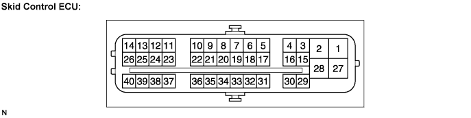
Symbols (Terminal No.)
| Terminal Description
|
GND4 (1)
| Skid control ECU ground
|
BS2 (2)
| FL, RR linear solenoid switching valve (SMC2) power supply
|
FLA+ (3)
| FL pressure increase linear solenoid (+) output
|
FLR+ (4)
| FL pressure decrease linear solenoid (+) output
|
SMC2 (5)
| Master cut solenoid 2 output
|
PCK2 (6)
| Pressure sensor 1 stuck check output
|
CANH (8)
| CAN communication line H
|
FLO (9)
| FL wheel speed signal output
|
RR+ (10)
| RR wheel speed sensor power supply output
|
LBL (11)
| Brake fluid level warning switch input
|
PMC2 (12)
| Master cylinder pressure sensor 2 signal input
|
FL+ (13)
| FL wheel speed sensor power supply output
|
IG2 (14)
| IG2 power supply
|
FLR- (15)
| FL pressure decrease linear solenoid (-) output
|
FLA- (16)
| FL pressure increase linear solenoid (-) output
|
RRA- (17)
| RR pressure increase linear solenoid (-) output
|
R2- (18)
| Motor relay 2 output
|
CANL (19)
| CAN communication line L
|
PKB (20)
| Parking brake switch input
|
RR- (23)
| RR wheel speed sensor input
|
VCM2 (24)
| Pressure sensor 2 power supply output
|
FL- (25)
| FL wheel speed sensor input
|
R2+ (26)
| Main relay 2 power supply output
|
BSO2 (28)
| SMC2 power supply output
|
RRA+ (29)
| RR pressure increase linear solenoid (+) output
|
RRR+ (30)
| RR pressure decrease linear solenoid (+) output
|
RRR- (31)
| RR pressure decrease linear solenoid (-) output
|
MR2 (32)
| Motor relay 2 power supply output
|
DI2 (33)
| +B input 2
|
DO2 (34)
| +B output 2
|
CBI2 (35)
| Capacitor power supply input 2
|
CSW (36)
| Traction OFF switch input
|
PRR (37)
| RR wheel cylinder pressure sensor signal input
|
E2 (38)
| Pressure sensor 2 ground
|
PFL (39)
| FL wheel cylinder pressure sensor signal input
|
R4+ (40)
| Main relay 2 output
|