ELECTRONICALLY CONTROLLED BRAKE SYSTEM > Skid Control Buzzer Circuit |

| 1.PERFORM ACTIVE TEST BY INTELLIGENT TESTER (SKID CONTROL BUZZER) |
Connect the intelligent tester to the DLC3.
Turn the engine switch on (IG) and turn the intelligent tester main switch on.
Select ACTIVE TEST mode on the intelligent tester.
| Item (Display) | Vehicle Condition/Test Details | Diagnostic Note |
| Buzzer | Turns skid control buzzer ON/OFF | Buzzer can be heard |
Check that the buzzer sounds/stops when turning the skid control buzzer on/off by using the intelligent tester.
| Condition | Proceed To |
| Buzzer sounds/stops | A |
| Buzzer does not sound or sounds constantly | B |
|
| ||||
| A | ||
| ||
| 2.INSPECT SKID CONTROL BUZZER (POWER SOURCE TERMINAL) |
 |
Disconnect the skid control buzzer connector.
Turn the engine switch on (IG).
Measure the voltage according to the value(s) in the table below.
| Tester Connection | Condition | Specified Condition |
| L11-2 - Body ground | Engine switch on (IG) | 10 to 14 V |
|
| ||||
| OK | |
| 3.INSPECT SKID CONTROL BUZZER |
 |
Disconnect the skid control buzzer connector.
Apply battery negative voltage to terminal 1, and battery positive voltage to terminal 2 of the skid control buzzer, and then check that the buzzer sounds.
|
| ||||
| OK | |
| 4.CHECK HARNESS AND CONNECTOR (SKID CONTROL ECU TO SKID CONTROL BUZZER) |
 |
Disconnect the skid control ECU connector.
Measure the resistance according to the value(s) in the table below.
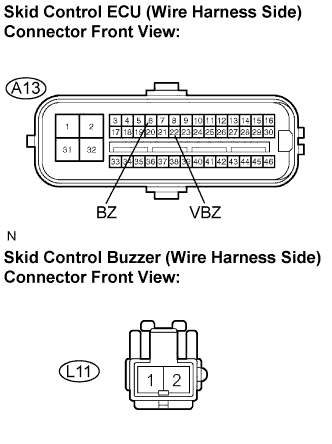
| Tester Connection | Specified Condition |
| A13-6 (BZ) - L11-1 | Below 1 Ω |
| A13-6 (BZ) - Body ground | 10 kΩ or higher |
| A13-22 (VBZ) - L11-2 | Below 1 Ω |
| A13-22 (VBZ) - Body ground | 10 kΩ or higher |
|
| ||||
| OK | |
| 5.INSPECT SKID CONTROL ECU (GND TERMINAL) |
 |
Disconnect the skid control ECU (A13, A15) connectors.
Measure the resistance according to the value(s) in the table below.
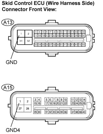
| Tester Connection | Specified Condition |
| A13-1 (GND) - Body ground | Below 1 Ω |
| A15-1 (GND4) - Body ground | Below 1 Ω |
|
| ||||
| OK | ||
| ||
