DTC P0200 Injector Circuit / Open |
DTC P0201 Injector Circuit / Open - (Cylinder 1) |
DTC P0202 Injector Circuit / Open - (Cylinder 2) |
DTC P0203 Injector Circuit / Open - (Cylinder 3) |
DTC P0204 Injector Circuit / Open - (Cylinder 4) |
DTC P0205 Injector Circuit / Open - (Cylinder 5) |
DTC P0206 Injector Circuit / Open - (Cylinder 6) |
DTC P12FF Electric Driver Unit |
| DTC No. | DTC Detection Condition | Trouble Area |
| P0200 |
|
|
| P0201 P0202 P0203 P0204 P0205 P0206 P12FF | NO INJF signals of each cylinder to ECM 20 times successively (1 trip detection logic) |
|
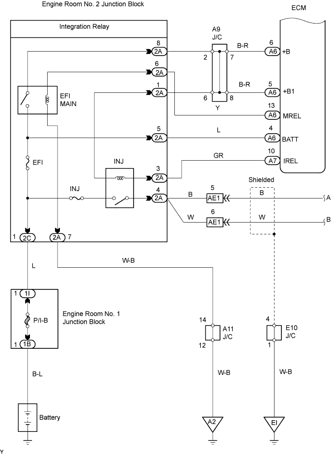
| 1.INSPECT INJECTOR DRIVER (POWER SOURCE OF EDU) |
 |
Disconnect the E52 EDU connector.
Turn the engine switch on (IG).
Measure the voltage between the specified terminals of the EDU connector.
| Tester Connection | Specified Condition |
| +B (E52-1) - Body ground | 9 to 14 V |
| +B2 (E52-2) - Body ground | 9 to 14 V |
Reconnect the EDU connector.
|
| ||||
| OK | |
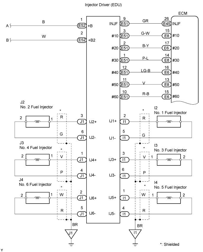
| 2.CHECK HARNESS AND CONNECTOR (EDU - FUEL INJECTOR) |
 |
Disconnect the I1 and J1 connectors.
Measure the resistance between the specified terminals of the EDU connector.
| Tester Connection | Specified Condition |
| IJ1+ (I1-2) - IJ1- (I1-5) | 2.01 to 2.31 Ω at 20°C (68°F) |
| IJ2+ (J1-3) - IJ2- (J1-6) | 2.01 to 2.31 Ω at 20°C (68°F) |
| IJ3+ (I1-3) - IJ3- (I1-6) | 2.01 to 2.31 Ω at 20°C (68°F) |
| IJ4+ (J1-1) - IJ4- (J1-4) | 2.01 to 2.31 Ω at 20°C (68°F) |
| IJ5+ (I1-1) - IJ5- (I1-4) | 2.01 to 2.31 Ω at 20°C (68°F) |
| IJ6+ (J1-2) - IJ6- (J1-5) | 2.01 to 2.31 Ω at 20°C (68°F) |
Reconnect the EDU connector.
|
| ||||
| OK | |
| 3.CHECK HARNESS AND CONNECTOR (ECM - EDU) |
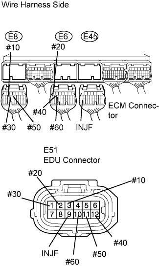 |
Disconnect the E6, E8 and E45 ECM connectors.
Disconnect the E51 EDU connector.
Measure the resistance between the wire harness side connectors.
| Tester Connection | Specified Condition |
| #10 (E8-15) - #10 (E51-3) | Below 1 Ω |
| #20 (E6-17) - #20 (E51-2) | Below 1 Ω |
| #30 (E8-14) - #30 (E51-1) | Below 1 Ω |
| #40 (E6-16) - #40 (E51-12) | Below 1 Ω |
| #50 (E8-13) - #50 (E51-11) | Below 1 Ω |
| #60 (E6-15) - #60 (E51-10) | Below 1 Ω |
| INJF (E45-26) - INJF (E51-9) | Below 1 Ω |
| Tester Connection | Specified Condition |
| #10 (E8-15) or #10 (E51-3) - Body ground | 10 kΩ or higher |
| #20 (E6-17) or #20 (E51-2) - Body ground | 10 kΩ or higher |
| #30 (E8-14) or #30 (E51-1) - Body ground | 10 kΩ or higher |
| #40 (E6-16) or #40 (E51-12) - Body ground | 10 kΩ or higher |
| #50 (E8-13) or #50 (E51-11) - Body ground | 10 kΩ or higher |
| #60 (E6-15) or #60 (E51-10) - Body ground | 10 kΩ or higher |
| INJF (E45-26) or INJF (E51-9) - Body ground | 10 kΩ or higher |
Reconnect the ECM connector.
Reconnect the EDU connector.
|
| ||||
| OK | |
| 4.CHECK ECM (#10, #20, #30, #40, #50 AND #60 VOLTAGE) |
 |
Connect an oscilloscope to terminals #10 to #60 and E1 of the E6, E7 and E8 ECM harness side connectors.
With the engine cranking or idling, check the signal waveform.
| ECM Terminal Name | CH1: #10 (E8-15) - E1 (E7-7) CH1: #20 (E6-17) - E1 (E7-7) CH1: #30 (E8-14) - E1 (E7-7) CH1: #40 (E6-16) - E1 (E7-7) CH1: #50 (E8-13) - E1 (E7-7) CH1: #60 (E6-15) - E1 (E7-7) |
| Tester Range | 20 V/DIV., 20 msec./DIV. |
| Condition | Idling after warming up engine |
|
| ||||
| OK | |
| 5.CHECK ECM (INJF VOLTAGE) |
 |
Connect an oscilloscope to terminals INJF and E1 of the E7 and E45 ECM harness side connectors.
With the engine cranking or idling, check the signal waveform.
| ECM Terminal Name | CH2: INJF (E45-26) - E1 (E7-7) |
| Tester Range | 20 V/DIV., 20 msec./DIV. |
| Condition | Idling after warming up engine |
|
| ||||
| OK | ||
| ||
| 6.INSPECT FUEL INJECTOR ASSEMBLY |
|
| ||||
| OK | ||
| ||
