VEHICLE STABILITY CONTROL SYSTEM > SYSTEM DESCRIPTION |
| SYSTEM DESCRIPTION |
ABS (Anti-lock Brake System)
The ABS helps prevent the wheels from locking when the brakes are applied firmly or when braking on a slippery surface.

Operation description
The skid control ECU detects wheel lock condition by receiving vehicle speed signals from each speed sensor, and sends control signals to the pump motor and solenoid valve. The pump motor and solenoid valve avoid wheel lock by controlling the brake fluid pressure of each wheel cylinder.
The ABS warning light comes on when the ABS system is malfunctioning.
EBD (Electronic Brake force Distribution)
The EBD control utilizes ABS, realizing proper brake force distribution between the front and rear wheels in accordance with driving conditions.
In addition, when braking while cornering, it also controls the brake forces of the right and left wheels, helping to maintain vehicle behavior.

Operation description
The skid control ECU receives the speed signal from each speed sensor to detect the slip condition of the wheels and sends the control signal to the solenoid.
The solenoid valve controls the fluid pressure of each wheel cylinder and splits the control power properly between the front and rear wheels and the right and left wheels.
The BRAKE warning light comes on to indicate a malfunction in the EBD system.
BA (Brake Assist)
The primary purpose of the brake assist system is to provide auxiliary brake force to assist the driver who cannot generate a large enough brake force during emergency braking, thus helping to maximize the vehicle's brake performance.
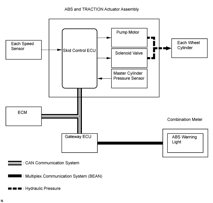
Operation description
The skid control ECU receives the speed signal from the each speed sensor and the fluid pressure signal from the master cylinder pressure sensor to determine whether brake assist is necessary or not. If brake assist is deemed necessary, the skid control ECU sends control signals to the pump motor and solenoid. The pump and the solenoid valve then control the pressure applied to each wheel cylinder.
The ABS warning light comes on to indicate a malfunction in the BA (brake assist) system.
TR(A)C (Traction Control)
The TR(A)C system helps prevent the drive wheels from slipping if the drive presses down on the accelerator pedal excessively when starting off or accelerating on a slippery surface.
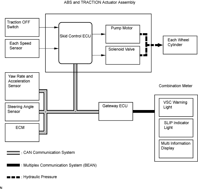
Operation description
The skid control ECU detects vehicle's slip condition by receiving signals from each speed sensor and ECM via CAN communication. The skid control ECU controls engine torque with the ECM via CAN communication and oil pressure through the pump and solenoid valve.
The SLIP indicator light blinks when the system is operating. If a malfunction occurs in the TR(A)C system, VSC warning light and SLIP indicator light will come on and the DTC will be displayed on the multi information display.
Traction OFF switch stops traction control operation.
VSC (Vehicle Stability Control)
The VSC system helps prevent the vehicle from slipping sideways as a result of strong front or rear wheel skid during cornering.
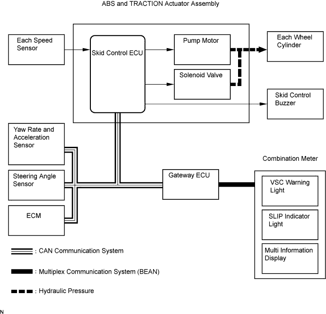
Operation description
The skid control ECU determines vehicle condition by receiving signals from the speed sensor, yaw rate and acceleration sensor and steering angle sensor. The skid control ECU controls engine torque with the ECM via CAN communication and fluid pressure with the pump and solenoid valve.
The SLIP indicator light blinks and the skid control buzzer sounds when the system is operating. If a malfunction occurs in the VSC system, VSC warning light and SLIP indicator light will come on and the DTC will be displayed on the multi information display.
| ABS with EBD, BA, TR(A)C and VSC OPERATION |
The skid control ECU calculates vehicle stability tendency based on the signals from the speed sensor, yaw rate and acceleration sensor and steering angle sensor. In addition, it evaluates the results of the calculations to determine whether any control actions (control of the engine output torque by electronic throttle control and of the wheel brake pressure by the ABS and TRACTION actuator assembly) should be implemented.
The SLIP indicator blinks and the skid control buzzer sounds to inform the drive that the VSC system is operating. The SLIP indicator also blinks when traction control is operating, and the operation being performed is displayed.
| FAIL SAFE |
When a failure occurs in the ABS with BA, TR(A)C and VSC systems, the ABS and VSC warning lights, and SLIP indicator light come on and ABS with BA, TR(A)C and VSC operations are prohibited. In addition to this, when there is a failure that disables the EBD operation, the BRAKE warning light also comes on and the EBD operation is prohibited (Click here).
If control is prohibited due to a malfunction during operation, control will be disabled gradually.
This is to avoid sudden vehicle instability.
| INITIAL CHECK |
When the vehicle speed first becomes approximately 4 mph (6 km/h) or more after the engine switch is turned on (IG), each solenoid valve and motor of the brake actuator is sequentially activated to perform an electrical check. During the initial check, the operating sound of solenoid valve and motor, can be heard from the engine compartment, but this is not a malfunction.
| SERVICE MODE |
VSC operation can be disables by operating the intelligent tester.
| FUNCTION OF COMPONENTS |
| Components | Function |
| Front speed sensor (Semiconductor speed sensor, magnetic sensor rotor) |
|
| Rear speed sensor (Semiconductor speed sensor, magnetic sensor rotor) |
|
| Skid control ECU (housed in ABS and TRACTION actuator assembly) |
|
| ABS and TRACTION actuator assembly |
|
| Solenoid relay |
|
| Motor relay (ABS MOTOR1 relay) |
|
| Fail-safe relay (ABS MOTOR2 relay) |
|
| Steering angle sensor |
|
| Yaw rate and acceleration sensor |
|
| Master cylinder pressure sensor |
|
| Brake pedal load sensing switch |
|
| ECM |
|
| Skid control buzzer |
|
| ABS warning light |
|
| BRAKE warning light |
|
| VSC warning light |
|
| SLIP indicator light |
|
| Multi information display |
|
| HILL-START ASSIST CONTROL |
When the vehicle starts off on a steep hill, HAC detects the backward descent of the vehicle and applies hydraulic pressure to the vehicle's brakes to reduce the reversing speed of the vehicle.
After a maximum of 5 seconds, fluid pressure is gradually released and control will be completed.
| DYNAMIC RADAR CRUISE CONTROL |
This system is designed to maintain an appropriate distance to the vehicle ahead, which is proportional to the vehicle speed. The distance to the vehicle ahead is measured based on signals sent from the millimeter wave radar sensor. To maintain the appropriate distance, this system controls the engine output, and also applies the brake if the distance to the vehicle ahead is too short.
| PRE-COLLISION SAFETY CONTROL |
The pre-collision safety system predicts frontal collisions with other vehicles or obstructions. By winding up the seat belts prior to collision, and performing brake control and brake assist control, it lessens the impact during the collision
The extremely high frequency radar recognizes if there is a vehicle or obstruction on the road ahead, and the distance control ECU makes a judgment from the position of the object, the speed and the road surface whether a collision is unavoidable.
The distance control ECU sends this information via a CAN communication to the seat belt control ECU, suspension control ECU and skid control ECU, to operate each control element of the pre-collision safety system.
