POWER WINDOW CONTROL SYSTEM > Front Passenger Side Power Window does not Operate with Front Passenger Side Power Window Switch |

| 1.CHECK REMOTE UP/DOWN FUNCTION |
Check that the front passenger side power window manual UP/DOWN function on the multiplex network master switch operates normally.
|
| ||||
| OK | ||
| ||
| 2.PERFORM ACTIVE TEST USING INTELLIGENT TESTER (POWER WINDOW UP/DOWN) |
Select the Active Test, use the intelligent tester to generate a control command, and then check the power window.
| Item | Test Details | Diagnostic Note |
| Power Window | UP/OFF (OFF) | - |
| Power Window | DOWN/OFF (OFF) | - |
|
| ||||
| OK | ||
| ||
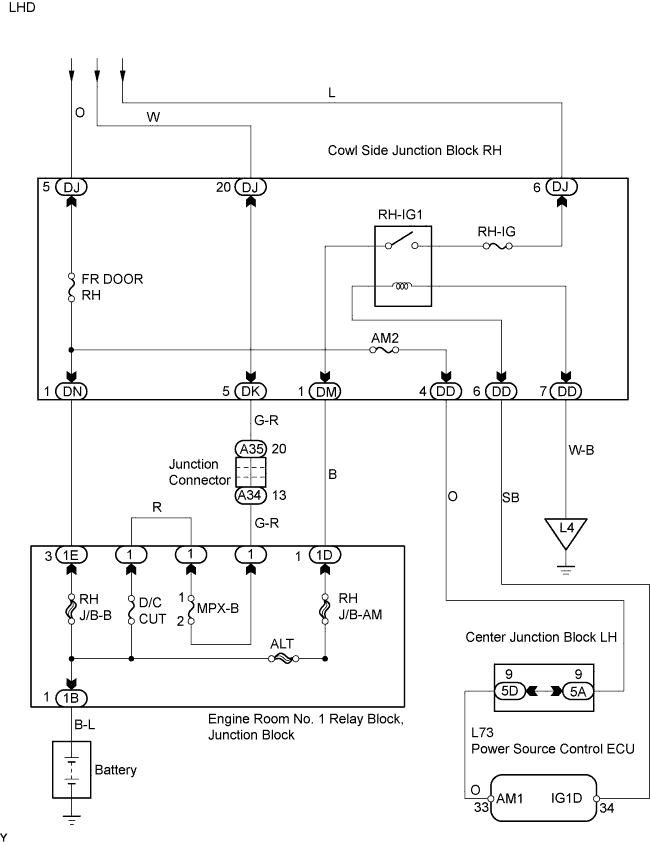
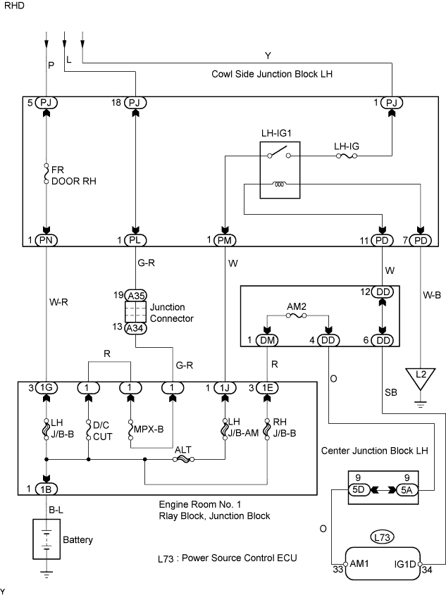
| 3.INSPECT FUSE (FR DOOR RH, RH-IG, AM2, D/C CUT, MPX-B) |
Remove the FR DOOR RH, RH-IG and AM2 fuses from the cowl side junction block RH.
Remove the MPX-B and D/C CUT fuses from the engine room No. 1 relay block.
Measure the resistance of the fuses.
|
| ||||
| OK | |
| 4.CHECK WIRE HARNESS (SWITCH ASSEMBLY (FRONT PASSENGER SIDE) - FRONT MOTOR ASSEMBLY (FRONT PASSENGER SIDE)) |
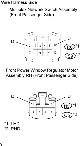 |
Disconnect the R6*1 or S9*2 switch connector.
Disconnect the N5*1 or O5*2 motor connector.
Measure the resistance of the wire harness side connectors.
| Tester Connection | Specified Condition |
| R6-6 (U) - N5-2 (U) | Below 1 Ω |
| R6-1 (D) - N5-1 (D) | Below 1 Ω |
| R6-6 (U) or N5-2 (U) - Body ground | 10 kΩ or higher |
| R6-1 (D) or N5-1 (D) - Body ground | 10 kΩ or higher |
| Tester Connection | Specified Condition |
| S9-6 (U) - O5-2 (U) | Below 1 Ω |
| S9-1 (D) - O5-1 (D) | Below 1 Ω |
| S9-6 (U) or O5-2 (U) - Body ground | 10 kΩ or higher |
| S9-1 (D) or O5-1 (D) - Body ground | 10 kΩ or higher |
|
| ||||
| OK | |
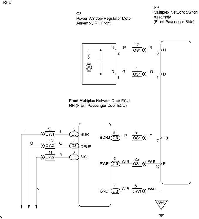
| 5.CHECK WIRE HARNESS (SWITCH ASSEMBLY (FRONT PASSENGER SIDE) - FRONT PASSENGER DOOR ECU) |
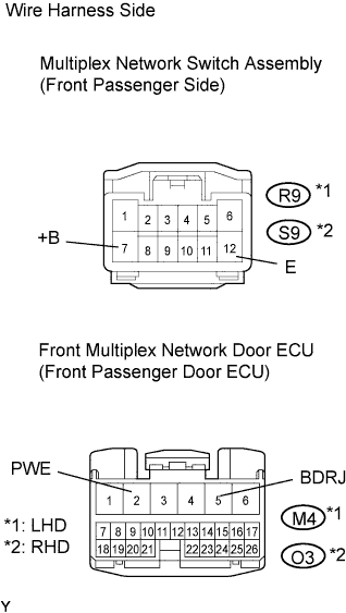 |
Disconnect the R9*1 or S9*2 switch connector.
Disconnect the M4*1 or O3*2 ECU connector.
Measure the resistance of the wire harness side connectors.
| Tester Connection | Specified Condition |
| R9-7 (+B) - M4-5 (BDRJ) | Below 1 Ω |
| R9-12 (E) - M4-2 (PWE) | Below 1 Ω |
| R9-7 (+B) or M4-5 (BDRJ) - Body ground | 10 kΩ or higher |
| R9-12 (E) or M4-2 (PWE) - Body ground | 10 kΩ or higher |
| Tester Connection | Specified Condition |
| S9-7 (+B) - O3-5 (BDRJ) | Below 1 Ω |
| S9-12 (E) - O3-2 (PWE) | Below 1 Ω |
| S9-7 (+B) or O3-5 (BDRJ) - Body ground | 10 kΩ or higher |
| S9-12 (E) or O3-2 (PWE) - Body ground | 10 kΩ or higher |
|
| ||||
| OK | |
| 6.CHECK WIRE HARNESS (FRONT PASSENGER DOOR ECU - BATTERY AND BODY GROUND) |
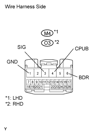 |
Disconnect the M4*1 or O3Z*2 ECU connector.
Measure the voltage and resistance of the wire harness side connector.
| Tester Connection | Condition | Specified Condition |
| M4-4 (CPUB) - Body ground | Always | 10 to 14 V |
| M4-6 (BDR) - Body ground | Always | 10 to 14 V |
| M4-3 (SIG) - Body ground | Engine switch on (IG) | 10 to 14 V |
| Tester Connection | Specified Condition |
| O3-4 (CPUB) - Body ground | 10 to 14 V |
| O3-6 (BDR) - Body ground | 10 to 14 V |
| O3-3 (SIG) - Body ground | 10 to 14 V |
| Tester Connection | Specified Condition |
| M4-1 (GND) - Body ground | Below 1 Ω |
| Tester Connection | Specified Condition |
| O3-1 (GND) - Body ground | Below 1 Ω |
|
| ||||
| OK | |
| 7.INSPECT FRONT POWER WINDOW REGULATOR MOTOR ASSEMBLY (FRONT PASSENGER SIDE) |
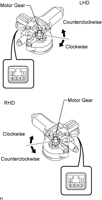 |
Remove the motor.
Apply battery voltage to connector terminals 1 and 2.
Check that the motor gear rotates smoothly as follows.
| Measurement Condition | Specified Condition |
| Battery positive (+) → 1 Battery negative (-) → 2 | Motor gear rotates clockwise |
| Battery positive (+) → 2 Battery negative (-) → 1 | Motor gear rotates counterclockwise |
| Measurement Condition | Specified Condition |
| Battery positive (+) → 2 Battery negative (-) → 1 | Motor gear rotates clockwise |
| Battery positive (+) → 1 Battery negative (-) → 2 | Motor gear rotates counterclockwise |
|
| ||||
| OK | |
| 8.CHECK OPERATION OF MULTIPLEX NETWORK SWITCH ASSEMBLY (PASSENGER SIDE) |
Temporarily replace the multiplex network switch assembly (front passenger side) with a new or normally functioning one.
Check that the power window operates normally.
|
| ||||
| OK | ||
| ||
