ENTRY AND START SYSTEM > TERMINALS OF ECU |
| CHECK POWER SOURCE CONTROL ECU |

Disconnect the L73 ECU connector.
Measure the voltage and resistance of the wire harness side connector.
| Symbols (Terminal No.) | Wiring Color | Terminal Description | Condition | Specified Condition |
| AM1 (L73-33) - Body ground | O - Body ground | +B power supply | Always | 10 to 14 V |
| AM2 (L73-12) - Body ground | BR - Body ground | +B power supply | Always | 10 to 14 V |
| SSW1 (L73-14) - Body ground | P - Body ground | Engine switch signal | Engine switch pushed | Below 1 Ω |
| SSW1 (L73-14) - Body ground | P - Body ground | Engine switch signal | Engine switch not pushed | 10 kΩ or higher |
| SSW2 (L73-37) - Body ground | B - Body ground | Engine switch signal | Engine switch pushed | Below 1 Ω |
| SSW2 (L73-37) - Body ground | B - Body ground | Engine switch signal | Engine switch not pushed | 10 kΩ or higher |
| GND2 (L73-6) - Body ground | W-B - Body ground | Ground | Always | Below 1 Ω |
| LIN1 (L73-30) - Body ground | W - Body ground | LIN line | Always | 10 kΩ or higher |
Reconnect the L73 ECU connector.
Measure the voltage of the connector.
| Symbols (Terminal No.) | Wiring Color | Terminal Description | Condition | Specified Condition |
| ACCD (L73-11) - GND2 (L73-6) | G - W-B | ACC signal | Engine switch on (ACC) | 10 to 14 V |
| ACCD (L73-11) - GND2 (L73-6) | G - W-B | ACC signal | Engine switch off | Below 1 V |
| IG1D (L73-34) - GND2 (L73-6) | SB - W-B | IG1 signal | Engine switch on (IG) | 10 to 14 V |
| IG1D (L73-34) - GND2 (L73-6) | SB - W-B | IG1 signal | Engine switch on (ACC) | Below 1 V |
| IG2D (L73-35) - GND2 (L73-6) | Y - W-B | IG2 signal | Engine switch on (IG) | 10 to 14 V |
| IG2D (L73-35) - GND2 (L73-6) | Y - W-B | IG2 signal | Engine switch on (ACC) | Below 1 V |
| STP (L73-1) - GND2 (L73-6) | V - W-B | Stop light signal | Brake pedal depressed | 10 to 14 V |
| STP (L73-1) - GND2 (L73-6) | V - W-B | Stop light signal | Brake pedal released | Below 1 V |
| SLR+ (L73-32) - GND2 (L73-6) | LG - W-B | Steering lock motor signal | Steering lock motor operating | Below 1 V |
| SLR+ (L73-32) - GND2 (L73-6) | LG - W-B | Steering lock motor signal | Steering lock motor does not operate | 10 to 14 V |
| SLP (L73-26) - GND2 (L73-6) | V - W-B | Steering lock actuator position signal | Steering lock is locked | 10 to 14 V |
| SLP (L73-26) - GND2 (L73-6) | V - W-B | Steering lock actuator position signal | Steering lock is released | Below 1 V |
| SPD (L73-19) - GND2 (L73-6) | L - W-B | Vehicle speed signal | Engine switch on (IG), rotate rear wheel slowly | Pulse generation (see waveform 1) |
| TACH (L73-2) - GND2 (L73-6) | W - W-B | Tachometer signal | Engine running | Pulse generation (see waveform 2) |
| P (L73-5) - GND2 (L73-6) | LG - W-B | Shift lock signal | Shift lever P position | 10 to 14 V |
| P (L73-5) - GND2 (L73-6) | LG - W-B | Shift lock signal | Shift lever not P position | Below 1 V |
| CTSW (L73-31) - GND2 (L73-6) | R - W-B | Starter assist signal | Brake pedal depressed, shift lever P position, engine switch is pushed once | Below 1 V*1
|
| STSW (L73-39) - GND2 (L73-6) | V - W-B | Starter activation request signal | Brake pedal depressed, shift lever P position, engine switch is pushed once | 10 to 14 V*2
|
| STR1 (L73-17) - GND2 (L73-6) | SB - W-B | Park/neutral position switch | Shift lever P position | Below 1 V |
| STR2 (L73-15) - GND2 (L73-6) | L - W-B | Starter signal | Brake pedal depressed, shift lever P position, engine switch is pushed once | 10 to 14 V*2
|
| INDS (L73-4) - GND2 (L73-6) | SB - W-B | Vehicle condition signal | Brake pedal depressed, shift lever P position, engine switch on (ACC, IG) | 10 to 14 V |
| INDW (L73-13) - GND2 (L73-6) | R - W-B | Warning signal | Brake pedal released, shift lever P position, engine switch on (ACC, IG) | 10 to 14 V |
| SWIL (L73-36) - GND2 (L73-6) | GR - W-B | Illumination signal | Light control switch TAIL or HEAD | 10 to 14 V |
Inspect using an oscilloscope.
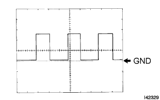 |
Waveform 1 (Reference)
| Item | Content |
| Symbols (Terminal No.) | SPD (L73-19) - Body ground |
| Tool Setting | 5 V/DIV., 10 msec./DIV. |
| Condition | Driving at approx. 20 km/h (12 mph) |
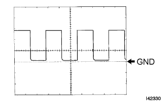 |
Waveform 2 (Reference)
| Item | Content |
| Symbols (Terminal No.) | TACH (L73-2) - Body ground |
| Tool Setting | 5 V/DIV., 10 msec./DIV. |
| Condition | Engine idling |
| CHECK CERTIFICATION ECU |
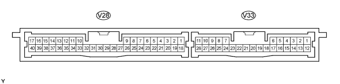
Disconnect the V28 and V33 ECU connectors.
Measure the voltage and resistance of the wire harness side connector.
| Symbols (Terminal No.) | Wiring Color | Terminal Description | Condition | Specified Condition |
| +B1 (V28-1) - Body ground | R - Body ground | +B power supply | Always | 10 to 14 V |
| IG (V28-18) - Body ground | B - Body ground | Ignition power supply | Engine switch on (IG) | 10 to 14 V |
| IG (V28-18) - Body ground | B - Body ground | Ignition power supply | Engine switch off | Below 1 V |
| LIN (V28-10) - Body ground | LG - Body ground | LIN line | Always | 10 kΩ or higher |
| E (V28-17) - Body ground | W-B - Body ground | Ground | Always | Below 1 Ω |
| CHECK ECM |

Disconnect the A6, E6, E7, E8 and E45 ECM connectors.
Measure the voltage and resistance of the wire harness side connectors.
| Symbols (Terminal No.) | Wiring Color | Terminal Description | Condition | Specified Condition |
| +B (A6-6) - Body ground | B-R - Body ground | Power source of ECM | Engine switch on (IG) | 10 to 14 V |
| +B1 (A6-5) - Body ground | B-R - Body ground | Power source of ECM | Engine switch on (IG) | 10 to 14 V |
| IGSW (A6-17) - Body ground | B-W - Body ground | Ignition switch signal | Engine switch on (IG) | 10 to 14 V |
| E01 (E6-2) - Body ground | W-B - Body ground | Ground | Always | Below 1 Ω |
| E02 (E6-1) - Body ground | W-B - Body ground | Ground | Always | Below 1 Ω |
| E03 (E8-6) - Body ground | W-B - Body ground | Ground | Always | Below 1 Ω |
| E04 (E45-5) - Body ground | W-B - Body ground | Ground | Always | Below 1 Ω |
| E05 (E45-3) - Body ground | W-B - Body ground | Ground | Always | Below 1 Ω |
| E1 (E7-7) - Body ground | BR - Body ground | Ground | Always | Below 1 Ω |
| EC (A6-2) - Body ground | W-B - Body ground | Ground | Always | Below 1 Ω |
| ME01 (E8-4) - Body ground | W-B - Body ground | Ground | Always | Below 1 Ω |
Reconnect the A6, E6, E7, E8 and E45 ECM connectors.
Measure the voltage of the connectors.
| Symbols (Terminal No.) | Wiring Color | Terminal Description | Condition | Specified Condition |
| STA (A6-12) - E1 (E7-7) | R - BR | Starter relay operation signal | Cranking | 10 to 14 V |
| ACCR (A6-11) - E1 (E7-7) | W-L - BR | ACC relay cut signal (output) | Engine switch on (IG) | 10 to 14 V |
| TACH (A7-16) - E1 (E7-7) | W-L - BR | Engine revolution signal (output) | Idling | Pulse generation (see waveform 1) |
| STP (A7-4) - E1 (E7-7) | R-B - BR | Stop light switch signal (input) | Brake pedal depressed | 7.5 to 14 V |
| STP (A7-4) - E1 (E7-7) | R-B - BR | Stop light switch signal (input) | Brake pedal released | Below 1.5 V |
| STAR (E7-4) - E1 (E7-7) | L-Y - BR | PNP switch signal (input) | Engine switch on (IG), shift position P or N | 10 to 14 V |
Inspect using an oscilloscope.
|
Waveform 1 (Reference)
| Item | Content |
| Symbols (Terminal No.) | TACH (A7-16) - Body ground |
| Tool Setting | 5 V/DIV., 10 msec./DIV. |
| Condition | Engine idling |
| CHECK STEERING LOCK ECU |

Disconnect the L28 ECU connector.
Measure the voltage and resistance of the wire harness side connector.
| Symbols (Terminal No.) | Wiring Color | Terminal Description | Condition | Specified Condition |
| B (L28-7) - Body ground | L - Body ground | +B power supply | Always | Always |
| IG2 (L28-6) - Body ground | B - Body ground | Ignition power supply | Engine switch on (IG) | Always |
| IG2 (L28-6) - Body ground | B - Body ground | Ignition power supply | Engine switch off | Below 1 V |
| GND (L28-1) - Body ground | W-B - Body ground | Ground | Always | Below 1 Ω |
| SGND (L28-2) - Body ground | W-B - Body ground | Ground | Always | Below 1 Ω |
Reconnect the L28 ECU connector.
Measure the voltage of the connector.
| Symbols (Terminal No.) | Wiring Color | Terminal Description | Condition | Specified Condition |
| SLP1 (L28-4) - GND (L28-1) | V - W-B | Steering lock actuator position signal | Steering is locked | 10 to 14 V |
| SLP1 (L28-4) - GND (L28-1) | V - W-B | Steering lock actuator position signal | Steering is released | Below 1 V |
