DTC C0210/33 Rear Speed Sensor RH Circuit |
DTC C0215/34 Rear Speed Sensor LH Circuit |
DTC C1273/73 Low Output Signal of Rear Speed Sensor RH (Test Mode DTC) |
DTC C1274/74 Low Output Signal of Rear Speed Sensor LH (Test Mode DTC) |
| DTC No. | DTC Detecting Condition | Trouble Area |
| C0210/33 C0215/34 | When any of the following is detected:
|
|
| 1.CHECK HARNESS AND CONNECTOR (MOMENTARY INTERRUPTION) |
Using the intelligent tester, check for any momentary interruption in the wire harness and connector corresponding to a DTC (Click here).
| Item (Display) | Measurement Item / Range (Display) | Normal Condition |
| RR Speed Open | RR speed sensor open detection / ERROR or NORMAL | ERROR: Momentary interruption NORMAL: Normal |
| RL Speed Open | RL speed sensor open detection / ERROR or NORMAL | ERROR: Momentary interruption NORMAL: Normal |
|
| ||||
| OK | |
| 2.READ VALUE OF INTELLIGENT TESTER (REAR SPEED SENSOR) |
Connect the intelligent tester to the DLC3.
Start the engine.
Select the DATA LIST mode on the intelligent tester.
| Item (Display) | Measurement Item / Range (Display) | Normal Condition |
| RL Wheel Speed | Wheel speed sensor (RL) reading / min.: 0 mph (0 km/h , max.: 202 mph (326 km/h)) | Actual wheel speed |
| RR Wheel Speed | Wheel speed sensor (RR) reading / min.: 0 mph (0 km/h , max.: 202 mph (326 km/h)) | Actual wheel speed |
Check that there is no difference between the speed value output from the speed sensor displayed on the intelligent tester and the speed value displayed on the speedometer when driving the vehicle.
| Item (Display) | Measurement Item / Range (Display) | Normal Condition |
| RR Wheel Direction | Wheel direction (RR) / FORWARD or BACK | FORWARD: Forward BACK: Back |
| RL Wheel Direction | Wheel direction (RL) / FORWARD or BACK | FORWARD: Forward BACK: Back |
Check that the sensor signal conforms to the wheel direction.
|
| ||||
| OK | |
| 3.PERFORM TEST MODE (SIGNAL CHECK) |
Perform sensor signal check in TEST MODE PROCEDURE (Click here).
|
| ||||
| OK | |
| 4.RECONFIRM DTC |
Clear the DTC (Click here).
Start the engine.
Drive the vehicle at the speed of 20 mph (32 km/h) or more for at least 60 seconds.
Check that the same DTC is recorded (Click here).
| Condition | Proceed To |
| DTCs (C0210/33 and C0215/34) are not output | A |
| DTCs (C0200/31 and C0205/32) are output | B |
|
| ||||
| A | ||
| ||
| 5.INSPECT REAR SPEED SENSOR INSTALLATION |
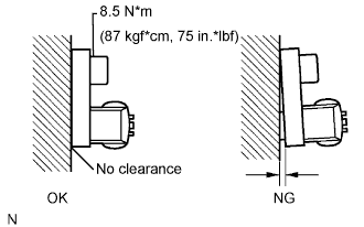 |
Check the sensor installation.
|
| ||||
| OK | |
| 6.INSPECT SPEED SENSOR TIP |
Remove the rear speed sensor (Click here).
Check the sensor tip.
|
| ||||
| OK | |
| 7.CHECK HARNESS AND CONNECTOR (SKID CONTROL SENSOR WIRE) |
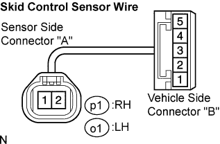 |
Disconnect the skid control sensor wire.
Measure the resistance according to the value(s) in the table below.
| Tester Connection | Specified Condition |
| p1 ("A"-2) - p1 ("B"-4) | Below 1 Ω |
| p1 ("A"-2) - p1 ("B"-5) | 10 kΩ or higher |
| p1 ("A"-2) - Body ground | 10 kΩ or higher |
| p1 ("A"-1) - p1 ("B"-5) | Below 1 Ω |
| p1 ("A"-1) - p1 ("B"-4) | 10 kΩ or higher |
| p1 ("A"-1) - Body ground | 10 kΩ or higher |
| Tester Connection | Specified Condition |
| o1 ("A"-2) - o1 ("B"-4) | Below 1 Ω |
| o1 ("A"-2) - o1 ("B"-5) | 10 kΩ or higher |
| o1 ("A"-2) - Body ground | 10 kΩ or higher |
| o1 ("A"-1) - o1 ("B"-5) | Below 1 Ω |
| o1 ("A"-1) - o1 ("B"-4) | 10 kΩ or higher |
| o1 ("A"-1) - Body ground | 10 kΩ or higher |
|
| ||||
| OK | |
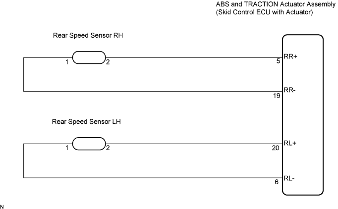
| 8.CHECK HARNESS AND CONNECTOR (SKID CONTROL ECU TO REAR SPEED SENSOR) |
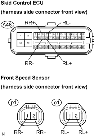 |
Disconnect the skid control ECU connector and the front speed sensor connector.
Measure the resistance according to the value(s) in the table below.
| Tester Connection | Specified Condition |
| A48-5 (RR+) - p1-2 (RR+) | Below 1 Ω |
| A48-19 (RR-) - p1-1 (RR-) | Below 1 Ω |
| Tester Connection | Specified Condition |
| A48-20 (RL+) - o1-2 (RL+) | Below 1 Ω |
| A48-6 (RL-) - o1-1 (RL-) | Below 1 Ω |
Measure the resistance according to the value(s) in the table below.
| Tester Connection | Specified Condition |
| A48-5 (RR+) - Body ground | 10 kΩ or higher |
| A48-19 (RR-) - Body ground | 10 kΩ or higher |
| Tester Connection | Specified Condition |
| A48-20 (RL+) - Body ground | 10 kΩ or higher |
| A48-6 (RL-) - Body ground | 10 kΩ or higher |
|
| ||||
| OK | |
| 9.INSPECT REAR SPEED SENSOR (INPUT VOLTAGE) |
 |
Disconnect the speed sensor connector.
Turn the engine switch on (IG).
Measure the voltage according to the value(s) in the table below.
| Tester Connection | Condition | Specified Condition |
| p1-2 (RR+) - Body ground | Engine switch on (IG) | 7.5 to 12 V |
| o1-2 (RL+) - Body ground | Engine switch on (IG) | 7.5 to 12 V |
|
| ||||
| OK | |
| 10.RECONFIRM DTC |
Clear the DTC (Click here).
Start the engine.
Drive the vehicle at the speed of 20 mph (32 km/h) or more for at least 60 seconds.
Check that the same DTC is recorded (Click here).
| Condition | Proceed To |
| DTCs (C0210/33 and C0215/34) are not output | A |
| DTCs (C0210/33 and C0215/34) are output | B |
|
| ||||
| A | ||
| ||
| 11.REPLACE REAR SPEED SENSOR |
Replace the rear speed sensor (Click here).
| NEXT | |
| 12.RECONFIRM DTC |
Clear the DTC (Click here).
Start the engine.
Drive the vehicle at the speed of 20 mph (32 km/h) or more for at least 60 seconds.
Check that the same DTC is recorded (Click here).
| Condition | Proceed To |
| DTCs (C0210/33 and C0215/34) are not output | A |
| DTCs (C0210/33 and C0215/34) are output | B |
|
| ||||
| A | ||
| ||
