DTC C0273/13 Open in ABS Motor Relay Circuit |
DTC C0274/14 Short to B+ in ABS Motor Relay Circuit |
DTC C1361/91 Short Circuit in ABS Motor Fail Safe Relay Circuit |
| DTC No. | DTC Detection Condition | Trouble Area |
| C0273/13 | When any of the following (1 or 2) is detected:
|
|
| C0274/14 | When the motor relay is OFF, the motor relay (ABS MOTOR1 relay) remains closed for 4 seconds or more. |
|
| C1361/91 | Immediately after the engine switch is turned on (IG), the relay contact is closed for 4 seconds when the motor fail-safe relay (ABS MOTOR2 relay) is OFF. |
|

| 1.INSPECT FUSE (ABS1 FUSE) |
Remove the ABS1 fuse from engine room R/B (J/B) No.1.
Measure the resistance according to the value(s) in the table below.
| Tester Connection | Specified Condition |
| ABS1 fuse | Below 1 Ω (Continuity) |
|
| ||||
| OK | |
| 2.INSPECT ABS MOTOR2 RELAY |
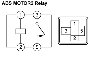 |
Remove the ABS MOTOR2 relay.
Measure the resistance according to the value(s) in the table below.
| Tester Connection | Condition | Specified Condition |
| 3 - 5 | Always | 10 kΩ or higher (No continuity) |
| 3 - 5 | Apply B+ between terminal 1 and 2 | Below 1 Ω (Continuity) |
|
| ||||
| OK | |
| 3.INSPECT ABS MOTOR1 RELAY |
 |
Remove the ABS MOTOR1 relay.
Measure the resistance according to the value(s) in the table below.
| Tester Connection | Condition | Specified Condition |
| 3 - 5 | Always | 10 kΩ or higher (No continuity) |
| 3 - 5 | Apply B+ between terminal 1 and 2 | Below 1 Ω (Continuity) |
|
| ||||
| OK | |
| 4.INSPECT ENGINE ROOM RELAY BLOCK NO.3 (POWER SOURCE TERMINAL) |
 |
Remove the ABS MOTOR1 relay from the engine room R/B No.3.
Measure the voltage according to the value(s) in the table below.
| Tester Connection | Condition | Specified Condition |
| ABS MOTOR1 relay terminal 5 - Body ground | Always | 10 to 14 V |
|
| ||||
| OK | |
| 5.INSPECT ENGINE ROOM RELAY BLOCK NO.3 |
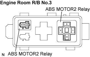 |
Measure the resistance according to the value(s) in the table below.
| Tester Connection | Specified Condition |
| ABS MOTOR1 relay terminal 3 - ABS MOTOR2 relay terminal 5 | Below 1 Ω |
|
| ||||
| OK | |
| 6.CHECK HARNESS AND CONNECTOR (SKID CONTROL ECU TO ENGINE ROOM RELAY BLOCK NO.3) |
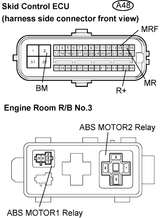 |
Disconnect the skid control ECU connector.
Remove the ABS MOTOR1 relay and ABS MOTOR2 relay from the engine room R/B No.3.
Measure the resistance according to the value(s) in the table below.
| Tester Connection | Specified Condition |
| A48-2 (BM) - ABS MOTOR2 relay 3 | Below 1 Ω |
| A48-14 (MRF) - ABS MOTOR1 relay 2 | Below 1 Ω |
| A48-15 (MR) - ABS MOTOR2 relay 2 | Below 1 Ω |
| A48-45 (R+) - ABS MOTOR1 relay 1 | Below 1 Ω |
Measure the resistance according to the value(s) in the table below.
| Tester Connection | Specified Condition |
| A48-2 (BM) - Body ground | 10 kΩ or higher |
| A48-14 (MRF) - Body ground | 10 kΩ or higher |
| A48-15 (MR) - Body ground | 10 kΩ or higher |
| A48-45 (R+) - Body ground | 10 kΩ or higher |
|
| ||||
| OK | |
| 7.RECONFIRM DTC |
Clear the DTC (Click here).
Start the engine.
Drive the vehicle at the speed of 4 mph (6 km/h) or more.
Check that the same DTC is recorded (Click here).
| Condition | Proceed To |
| DTCs (C0273/13, C0274/14 and C1361/91) are not output | A |
| DTCs (C0273/13, C0274/14 and C1361/91) are output | B |
|
| ||||
| A | ||
| ||
