DTC C1235/35 Foreign Object is Attached on Tip of Front Speed Sensor RH |
DTC C1236/36 Foreign Object is Attached on Tip of Front Speed Sensor LH |
DTC C1238/38 Foreign Object is Attached on Tip of Rear Speed Sensor RH |
DTC C1239/39 Foreign Object is Attached on Tip of Rear Speed Sensor LH |
DTC C1275/75 Abnormal Change in Output Signal of Front Speed Sensor RH (Test Mode DTC) |
DTC C1276/76 Abnormal Change in Output Signal of Front Speed Sensor LH (Test Mode DTC) |
DTC C1277/77 Abnormal Change in Output Signal of Rear Speed Sensor RH (Test Mode DTC) |
DTC C1278/78 Abnormal Change in Output Signal of Rear Speed Sensor LH (Test Mode DTC) |
| DTC No. | DTC Detecting Condition | Trouble Area |
| C1235/35 C1236/36 C1238/38 C1239/39 | When either of the following is detected:
|
|
| 1.CHECK HARNESS AND CONNECTOR (SKID CONTROL ECU TO SPEED SENSOR) |
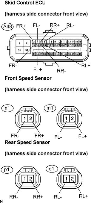 |
Disconnect the skid control ECU connector and the speed sensor connector.
Measure the resistance according to the value(s) in the table below.
| Tester Connection | Specified Condition |
| A48-3 (FR+) - n1-2 (FR+) | Below 1 Ω |
| A48-17 (FR-) - n1-1 (FR-) | Below 1 Ω |
| A48-5 (RR+) - p1-2 (RR+) | Below 1 Ω |
| A48-19 (RR-) - p1-1 (RR-) | Below 1 Ω |
| Tester Connection | Specified Condition |
| A48-18 (FL+) - m1-2 (FL+) | Below 1 Ω |
| A48-4 (FL-) - m1-1 (FL-) | Below 1 Ω |
| A48-20 (RL+) - o1-2 (RL+) | Below 1 Ω |
| A48-6 (RL-) - o1-1 (RL-) | Below 1 Ω |
Measure the resistance according to the value(s) in the table below.
| Tester Connection | Specified Condition |
| A48-3 (FR+) - Body ground | 10 kΩ or higher |
| A48-17 (FR-) - Body ground | 10 kΩ or higher |
| A48-5 (RR+) - Body ground | 10 kΩ or higher |
| A48-19 (RR-) - Body ground | 10 kΩ or higher |
| Tester Connection | Specified Condition |
| A48-18 (FL+) - Body ground | 10 kΩ or higher |
| A48-4 (FL-) - Body ground | 10 kΩ or higher |
| A48-20 (RL+) - Body ground | 10 kΩ or higher |
| A48-6 (RL-) - Body ground | 10 kΩ or higher |
|
| ||||
| OK | |
| 2.INSPECT SPEED SENSOR (INPUT VOLTAGE) |
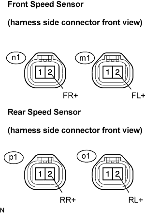 |
Disconnect the speed sensor connector.
Turn the engine switch to the on (IG).
Measure the voltage according to the value(s) in the table below.
| Tester Connection | Condition | Specified Condition |
| n1-2 (FR+) - Body ground | Engine switch on (IG) | 7.5 to 12 V |
| m1-2 (FL+) - Body ground | Engine switch on (IG) | 7.5 to 12 V |
| p1-2 (RR+) - Body ground | Engine switch on (IG) | 7.5 to 12 V |
| o1-2 (RL+) - Body ground | Engine switch on (IG) | 7.5 to 12 V |
|
| ||||
| OK | |
| 3.RECONFIRM DTC |
Clear the DTC (Click here).
Start the engine.
Drive the vehicle at the speed of 12 mph (20 km/h) or more for at least 60 seconds.
Check that the same DTC is recorded (Click here).
| Condition | Proceed To |
| DTCs (C1235/35 and C1236/36, C1238/38 and C1239/39) are output | A |
| DTCs (C1235/35 and C1236/36, C1238/38 and C1239/39) are not output | B |
|
| ||||
| A | |
| 4.INSPECT SPEED SENSOR TIP |
Remove the each speed sensor (Click here for front, or Click here for rear).
Check the sensor tip.
|
| ||||
| OK | ||
| ||
