VEHICLE STABILITY CONTROL SYSTEM > ABS Warning Light Remains ON |

| 1.INSPECT CAN COMMUNICATION SYSTEM |
Check if the CAN communication system DTC is output (Click here).
| Condition | Proceed To |
| DTC is not output | A |
| DTC is output | B |
|
| ||||
| A | |
| 2.INSPECT MULTIPLEX COMMUNICATION SYSTEM |
Check if the multiplex communication system DTC is output (Click here).
| Condition | Proceed To |
| DTC is not output | A |
| DTC is output | B |
|
| ||||
| A | |
| 3.INSPECT IF SKID CONTROL ECU CONNECTOR IS SECURELY CONNECTED |
Check the skid control ECU connector's connecting condition.
|
| ||||
| OK | |
| 4.INSPECT BATTERY |
Check the battery voltage.
|
| ||||
| OK | |
| 5.INSPECT SKID CONTROL ECU (IG TERMINAL) |
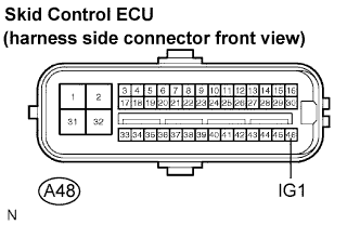 |
Disconnect the skid control ECU connector.
Turn the engine switch to the on (IG).
Measure the voltage according to the value(s) in the table below.
| Tester Connection | Condition | Specified Condition |
| A48-46 (IG1) - Body ground | Engine switch on (IG) | 10 to 14 V |
|
| ||||
| OK | |
| 6.INSPECT SKID CONTROL ECU (GND TERMINAL) |
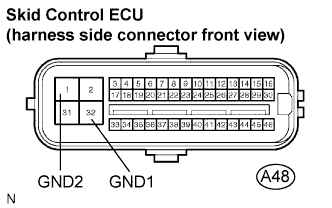 |
Disconnect the skid control ECU connector.
Measure the resistance according to the value(s) in the table below.
| Tester Connection | Specified Condition |
| A48-32 (GND1) - Body ground | Below 1 Ω |
| A48-1 (GND2) - Body ground | Below 1 Ω |
|
| ||||
| OK | |
| 7.INSPECT COMBINATION METER ASSEMBLY |
Check the combination meter assembly (Click here).
|
| ||||
| OK | ||
| ||
