C1267/67
| When any of the following is detected:
- An open or short in the brake pedal load sensing switch continues for 0.3 seconds or more.
- Immediately after the engine switch is turned on (IG), the brake pedal load sensing switch is ON and the stop light switch is OFF for 10 seconds or more.
- While the vehicle speed changes from 0 mph (0 km/h) to 18 mph (30 km/h), the condition that the brake pedal load sensing switch remains ON occurs 5 times in succession.
- With the stop light switch ON, the brake pedal load sensing switch OFF, and the master cylinder pressure 6 Mpa or more, the deceleration is 0.4 G or more for 1 second or more.
- With the stop light switch ON, the brake pedal load sensing switch OFF, and the master cylinder pressure 6 Mpa or more, the vehicle speed is 0 mph (0 km/h) for 5 seconds or more.
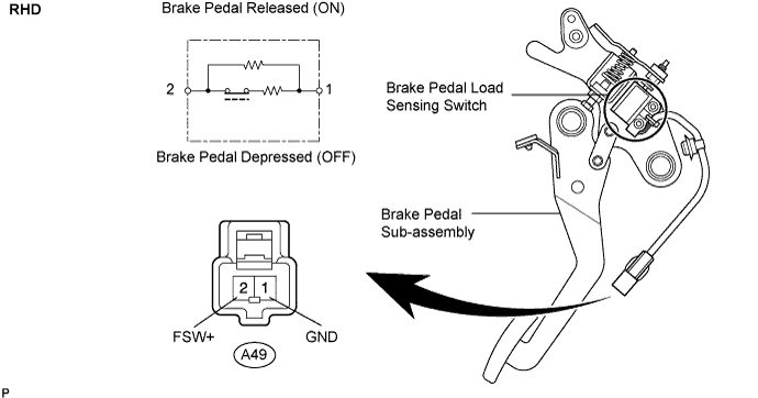
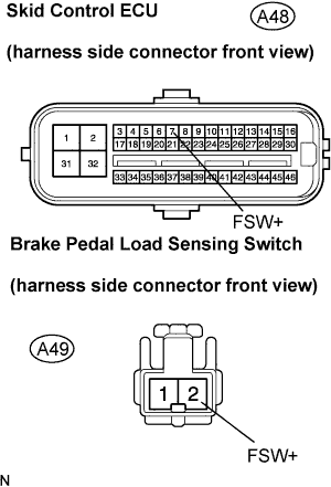
| - Brake pedal load sensing switch
- Brake pedal load sensing switch circuit
|