VEHICLE STABILITY CONTROL SYSTEM > TC and CG Terminal Circuit |
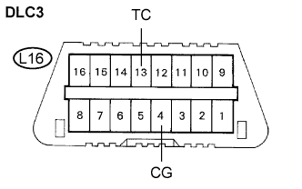
| 1.INSPECT DLC3 TERMINAL VOLTAGE (TC TERMINAL VOLTAGE) |
 |
Turn the engine switch on (IG).
Measure the voltage according to the value(s) in the table below.
| Tester Connection | Condition | Specified Condition |
| L16-13 (TC) - Body ground | Engine switch on (IG) | 10 to 14 V |
Measure the resistance according to the value(s) in the table below.
| Tester Connection | Specified Condition |
| L16-4 (CG) - Body ground | Below 1 Ω |
|
| ||||
| OK | |
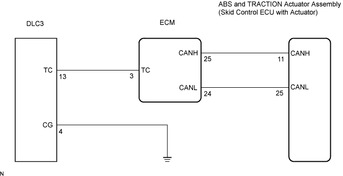
| 2.CHECK HARNESS AND CONNECTOR (ECM TO DLC3) |
 |
Disconnect the ECM connector.
Measure the resistance according to the value(s) in the table below.
| Tester Connection | Specified Condition |
| L16-13 (TC) - A7-3 (TC) | Below 1 Ω |
Measure the resistance according to the value(s) in the table below.
| Tester Connection | Specified Condition |
| L16-13 (TC) - Body ground | 10 kΩ or higher |
|
| ||||
| OK | |
| 3.CHECK CAN COMMUNICATION SYSTEM |
Check if the CAN communication DTC is output (Click here).
| Condition | Proceed To |
| DTC is not output | A |
| DTC is output | B |
|
| ||||
| A | ||
| ||
| 4.CHECK HARNESS AND CONNECTOR (ECM TO DLC3) |
|
Disconnect the ECM connector.
Measure the resistance according to the value(s) in the table below.
| Tester Connection | Specified Condition |
| L16-13 (TC) - A7-3 (TC) | Below 1 Ω |
Measure the resistance according to the value(s) in the table below.
| Tester Connection | Specified Condition |
| L16-13 (TC) - Body ground | 10 kΩ or higher |
|
| ||||
| OK | |
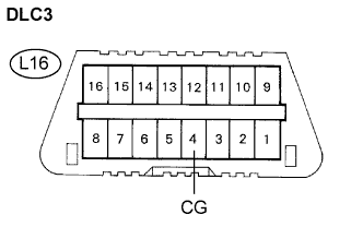
| 5.CHECK HARNESS AND CONNECTOR (DLC3 TO BODY GROUND) |
 |
Measure the resistance according to the value(s) in the table below.
| Tester Connection | Specified Condition |
| L16-4 (CG) - Body ground | Below 1 Ω |
|
| ||||
| OK | |
| 6.CHECK ECM (DLC3 (TC) INPUT) |
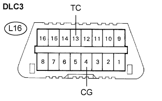 |
Using the SST, connect terminals TC and CG of the DLC3.
Check that the engine warning light is blinking.
| Condition | Proceed To |
| Engine warning light is blinking | A |
| Engine warning light is not blinking | B |
|
| ||||
| A | |
| 7.CHECK CAN COMMUNICATION SYSTEM |
Check if the CAN communication system DTC is output (Click here).
| Condition | Proceed To |
| DTC is not output | A |
| DTC is output | B |
|
| ||||
| A | ||
| ||
