TIRE PRESSURE WARNING SYSTEM > DIAGNOSIS SYSTEM |
| CHECK BATTERY VOLTAGE |
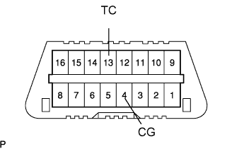 |
| CHECK DLC3 |
| Terminal No. | Disc. | Connection / Voltage or Resistance | Condition |
| 7 | SIL | Bus + Line / Pulse generation | During transmission |
| 4 | CG | Chassis Ground to Body Ground / 1 Ω or less | Always |
| 16 | BAT | Battery Positive to Body Ground / 10 to 14 V | Always |
| DIAGNOSIS SYSTEM |
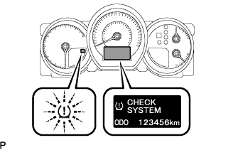 |
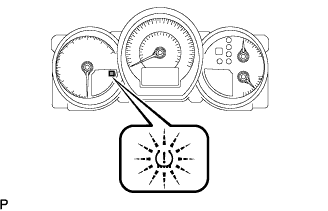
Warning light and indicator
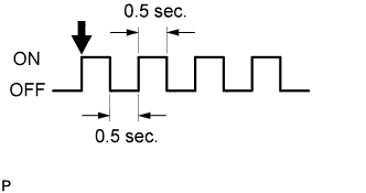
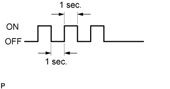
When there is a problem with the tire pressure warning system, the "CHECK SYSTEM" displayed on the multi-display and the tire pressure warning light blinks at 0.5 second intervals.
DTCs (Normal mode)
DTCs are memorized in the tire pressure monitor ECU and read by the blinks of the tire pressure warning light or using the intelligent tester (Click here).
Test mode
By switching from normal mode into test mode (input signal check), you can inspect the tire pressure monitor receiver assembly, each tire pressure monitor valve sub-assembly and vehicle speed sensor (Click here).
| CHECK WARNING LIGHT |
 |
Turn the engine switch on (IG).
Check that the tire pressure warning light comes on for 3 seconds.
If the warning check result is not normal, proceed to the troubleshooting for the tire pressure warning light circuit.
| Trouble Area | See procedure |
| Tire pressure warning light circuit |
Click here
|
| TIRE PRESSURE WARNING LIGHT AND INDICATOR CHART |
| Immediately after turning the engine switch on (IG) | Always | ||||||
| Warning light output pattern | Warning indicator output pattern | ||||||
| Comes on for 3 sec. | Goes off | Comes on | Blink (*1) | Blinks (*2) | Blinks (*3) | Displayed on multi-information display | |
| Normal | ○ | ○ | - | ||||
| Low tire pressure | ○ | ○ | LOW TIRE | ||||
| System fail | ○ | ○ | CHECK SYSTEM | ||||
| Test mode | ○ | ○ | TEST MODE | ||||
| Initialization | ○ | ○ | PRESSURE INITIAL (*4) | ||||
| ECU connector poorly connected | ○ | - | |||||
| TC ground | ○ | DIAG TIRE OK (*5) | |||||
 |
 |
 |
