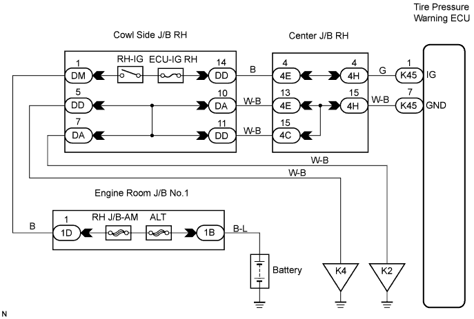
TIRE PRESSURE WARNING SYSTEM > ECU Power Source Circuit |
| 1.INSPECT BATTERY |
Check the battery voltage.
|
| ||||
| OK | |
| 2.INSPECT FUSE (ECU-IG) |
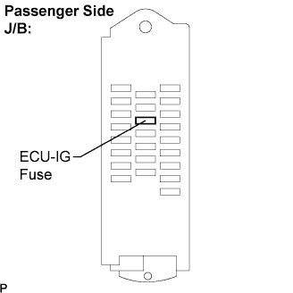 |
Remove the ECU-IG fuse from the passenger side J/B.
Check continuity of the ECU-IG fuse.
|
| ||||
| OK | |
| 3.INSPECT TIRE PRESSURE MONITOR ECU |
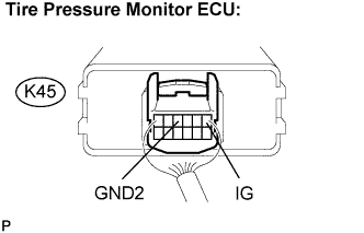 |
Remove the tire pressure monitor ECU with connectors being connected.
Turn the engine switch on (IG).
Measure the voltage according to the value(s) in the table below.
| Tester Connection | Specified Condition |
| K45-1 (IG) - K45-4 (GND2) | 10 to 14 V |
|
| ||||
| OK | ||
| ||
| 4.CHECK HARNESS AND CONNECTOR (BATTERY - TIRE PRESSURE MONITOR ECU) |
 |
Disconnect the tire pressure monitor ECU K45 connector.
Turn the engine switch on (IG).
Measure the voltage according to the value(s) in the table below.
| Tester Connection | Specified Condition |
| K45-1 (IG) - Body ground | 10 to 14 V |
|
| ||||
| OK | |
| 5.CHECK HARNESS AND CONNECTOR (TIRE PRESSURE MONITOR ECU - BODY GROUND) |
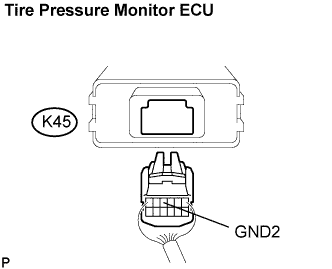 |
Disconnect the tire pressure monitor ECU K45 connector.
Measure the resistance according to the value(s) in the table below.
| Tester Connection | Specified Condition |
| K45-4 (GND2) - Body ground | Below 1 Ω |
|
| ||||
| OK | ||
| ||
