TIRE PRESSURE WARNING SYSTEM > Tire Pressure Warning Reset Switch Circuit |
| 1.CHECK TIRE PRESSURE WARNING RESET SWITCH FUNCTION |
Perform the tire pressure warning reset switch test in TEST MODE PROCEDURE (Click here).
|
| ||||
| OK | ||
| ||
| 2.INSPECT TIRE PRESSURE WARNING RESET SWITCH |
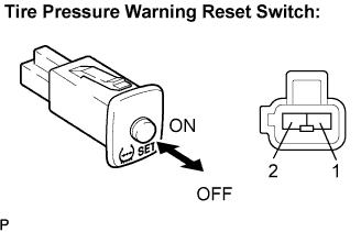 |
Disconnect the tire pressure warning reset switch connector.
Measure the resistance between terminals 1 and 2 of the tire pressure warning reset switch when the tire pressure warning switch is ON and OFF.
| Switch Condition | Specified Condition |
| ON | Below 1 Ω |
| OFF | 10 kΩ or higher |
|
| ||||
| OK | |
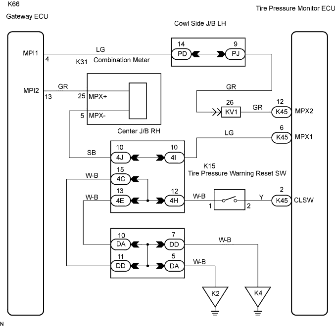
| 3.CHECK HARNESS AND CONNECTOR (TIRE PRESSURE WARNING RESET SWITCH-TIRE PRESSURE MONITOR ECU) |
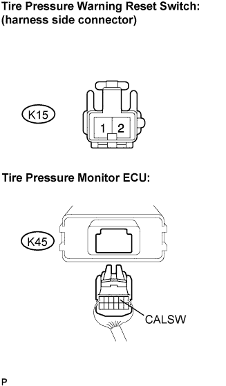 |
Disconnect the tire pressure warning reset switch K15 connector and tire pressure monitor ECU K45 connector.
Measure the resistance according to the value(s) in the table below.
| Tester Connection | Specified Condition |
| K45-2 (CALSW) - K15-1 | Below 1 Ω |
| K45-2 (CALSW) - Body ground | 10 kΩ or higher |
|
| ||||
| OK | ||
| ||
