FUEL LID OPENER SYSTEM > TERMINALS OF ECU |
| CHECK COWL SIDE JUNCTION BLOCK LH (MULTIPLEX NETWORK BODY ECU) |
Disconnect the PA, PD and PL junction block connectors.
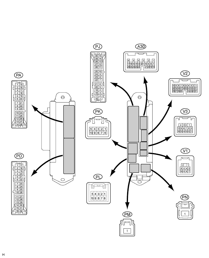
Measure the voltage and resistance of the wire harness side connectors.
| Symbols (Terminal No.) | Wiring Color | Terminal Description | Condition | Specified Condition |
| GND (PA-14) - Body ground | W-B - Body ground | Ground | Always | Below 1 Ω |
| SGNB (PD-8) - Body ground | W-B - Body ground | Ground | Always | Below 1 Ω |
| SGNB (PD-7) - Body ground | W-B - Body ground | Ground | Always | Below 1 Ω |
| MPXB (PL-1) - Body ground | G-R - Body ground | Battery power supply | Always | 10 to 14 V |
Reconnect the PA, PD and PL junction block connectors.
Measure the voltage of the wire harness side connectors.
| Symbols (Terminal No.) | Wiring Color | Terminal Description | Condition | Specified Condition |
| RFRL (PM-1) - Body ground | W - Body ground | FUEL OPEN relay signal | Fuel lid opener motor is not actuated | 10 to 14 V |
| RFRL (PM-1) - Body ground | W - Body ground | FUEL OPEN relay signal | Fuel lid opener motor is actuated | Below 1 V |
| RFRL (PJ-25) Body ground | V - Body ground | Fuel lid opener motor actuating signal | Fuel lid opener motor is not actuated | 10 to 14 V |
| RFRL (PJ-25) Body ground | V - Body ground | Fuel lid opener motor actuating signal | Fuel lid opener motor is actuated | Below 1 V |
| CHECK INTEGRATION CONTROL AND PANEL ASSEMBLY |
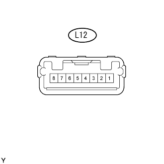
Disconnect the L12 panel connector.
Measure the voltage and resistance of the wire harness side connector.
| Symbols (Terminal No.) | Wiring Color | Terminal Description | Condition | Specified Condition |
| GND (L12-2) - Body ground | W-B - Body ground | Ground | Always | Below 1 Ω |
| +B (L12-6) - Body ground | L - Body ground | Ground | Always | 10 to 14 V |
