FUEL LID OPENER SYSTEM > Fuel Lid Opener does not Operate |
| 1.INSPECT FUSE (FUEL OPEN) |
Remove the FUEL OPEN fuse from the cowl side junction block LH.
Measure the resistance of the fuse.
|
| ||||
| OK | |
| 2.READ VALUE OF DATA LIST (FUEL LID OPENER SWITCH) |
Use the Data List to check if the switch is functioning properly.
| Item | Measurement Item/Display (Range) | Normal Condition | Diagnostic Note |
| FUEL Lid Opn SW | Fuel lid opener switch signal ON / or OFF | ON: Fuel lid opener switch is pressed OFF: Fuel lid opener switch is not pressed | - |
|
| ||||
| OK | |
| 3.PERFORM ACTIVE TEST BY INTELLIGENT TESTER (FUEL LID OPENER MOTOR) |
Select the Active Test, use the intelligent tester to generate a control command, and then check that the fuel lid opener motor operates normally.
| Item | Test Details | Diagnostic Note |
| FUEL Lid Open SW | Operate fuel lid opener motor ON: Fuel lid is opened OFF: Fuel lid is not opened | - |
|
| ||||
| OK | ||
| ||
| 4.INSPECT FUEL LID MOTOR LOCK ASSEMBLY |
 |
Apply battery voltage to the lock and check operation of the lock.
| Measurement Condition | Specified Condition |
| Battery positive (+) → Terminal 2 Battery negative (-) → Terminal 1 | Shaft moves to open direction |
Check the shaft strokes.
|
| ||||
| OK | |
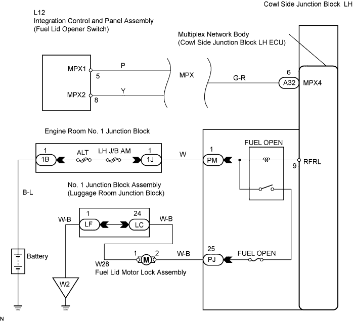
| 5.CHECK WIRE HARNESS (COWL SIDE JUNCTION BLOCK LH - BATTERY) |
 |
Disconnect the PM junction block connector.
Measure the voltage.
| Tester Connection | Specified Condition |
| PM-1 - Body ground | 10 to 14 V |
|
| ||||
| OK | |
| 6.CHECK WIRE HARNESS (FUEL LID MOTOR LOCK ASSEMBLY - COWL SIDE JUNCTION BLOCK LH AND BODY GROUND) |
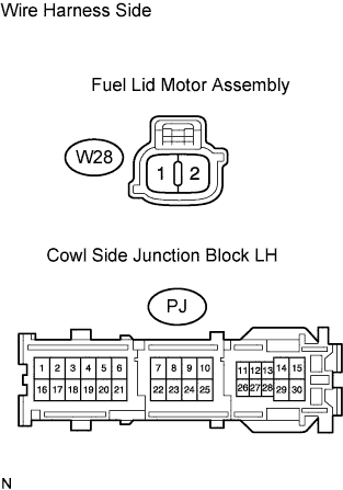 |
Disconnect the W28 motor connector.
Disconnect the PJ junction block connector.
Measure the resistance of the wire harness side connectors.
| Tester Connection | Specified Condition |
| W28-2 - PJ-25 | Below 1 Ω |
| W28-1 - Body ground | Below 1 Ω |
|
| ||||
| OK | ||
| ||
