VARIABLE GEAR RATIO STEERING SYSTEM > DIAGNOSIS SYSTEM |
| DIAGNOSTIC SYSTEM |
 |
Inspect the battery voltage.
Check the DLC3.
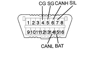
The steering control ECU uses CAN and ISO 9141-2 as its communication protocol. The terminal arrangement of the DLC3 complies with ISO 15031-3and matches the ISO 9141-2 format. Verify the conditions listed in the table below.
| Symbols (Terminals No.) | Terminal description | Condition | Specified condition |
| SIL (7) - SG (5) | Bus "+" line | During transmission | Pulse generation |
| CG (4) - Body ground | Chassis ground | Always | Below 1 Ω |
| SG (5) - Body ground | Signal ground | Always | Below 1 Ω |
| BAT (16) - Body ground | Battery positive | Always | 11 to 14 V |
| CANH (6) - CANL (14) | HIGH-level CAN bus line | Engine switch off | 54 to 67 Ω |
| CANH (6) - Battery positive | HIGH-level CAN bus line | Engine switch off | 1 MΩ or higher |
| CANH (6) - CG (4) | HIGH-level CAN bus line | Engine switch off | 3 kΩ or higher |
| CANL (14) - Battery positive | LOW-level CAN bus line | Engine switch off | 1 MΩ or higher |
| CANL (14) - CG (4) | LOW-level CAN bus line | Engine switch off | 3 kΩ or higher |
| FUNCTION OF WARNING LIGHT AND MESSAGE |
 |
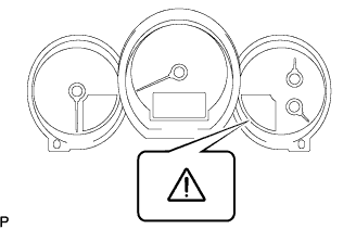
If a malfunction occurs during system operation, the master warning light (VGRS) on the combination meter assembly will come on and "CHECK VGRS" will be displayed on the multi-information display to inform the driver of the system malfunction.
| DTCs |
 |
Normal mode.
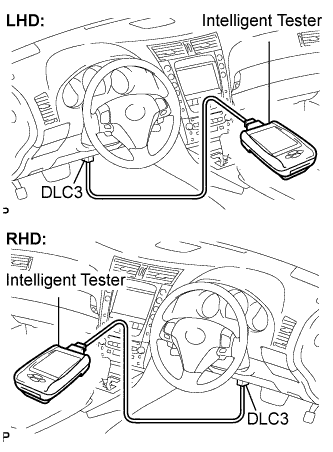
DTCs are memorized in the steering control ECU and read by using the intelligent tester (Click here).
Test mode.
By switching from normal mode to test mode, the steering angle sensor can be inspected (Click here).
| CHECK MASTER WARNING LIGHT |
 |
Turn the engine switch on (IG).
Check that the master warning light (VGRS) comes on for 2 seconds.
| Trouble Area | See procedure |
| Master warning light circuit |
Click here
|
