VARIABLE GEAR RATIO STEERING SYSTEM > CHECK MODE PROCEDURE |
| TEST MODE (VGRS SENSOR SIGNAL CHECK) |
 |
 |
Check the test mode DTCs (using the intelligent tester).
Turn the engine switch off.
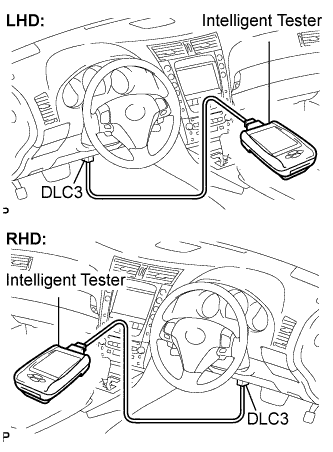
Connect the intelligent tester to the DLC3.
Turn the engine switch on (IG) and turn the intelligent tester on.
Read the test mode DTCs by following the prompts on the tester screen.
|
Clear the test mode DTCs (using the intelligent tester).
Turn the engine switch off.
Connect the intelligent tester to the DLC3.
Turn the engine switch on (IG) and turn the intelligent tester on.
Switch the system from test mode to normal mode by following the directions on the tester screen.
Check the test mode DTCs (using SST check wire).
Turn the engine switch off.
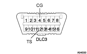 |
Using SST check wire, connect terminals TS (TC) and CG of the DLC3.
Turn the engine switch on (IG).
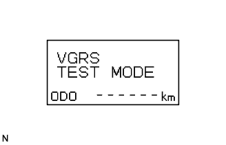
Read 2-digit test mode DTCs from the multi-information display.
Clear the test mode DTCs (using SST check wire).
Turn the engine switch off.
Disconnect the SST check wire from the DLC3.
Turn the engine switch on (IG).
| TEST MODE DTC |
If a trouble code is displayed during the DTC check, check the circuit indicated by the DTC. For details of each code, proceed to DTC chart.
| DTC No. | Detection Item | Trouble Area |
| C15C4/74 | A steering signal indicating a tire angle of 36°or more (to the left or right) is input after transfer to test mode. (*1) |
|
| C15C5/75 | A steering signal indicating a motor rotation angle of 36°or more (to the left or right) is input after transfer to test mode. (*1) |
|
