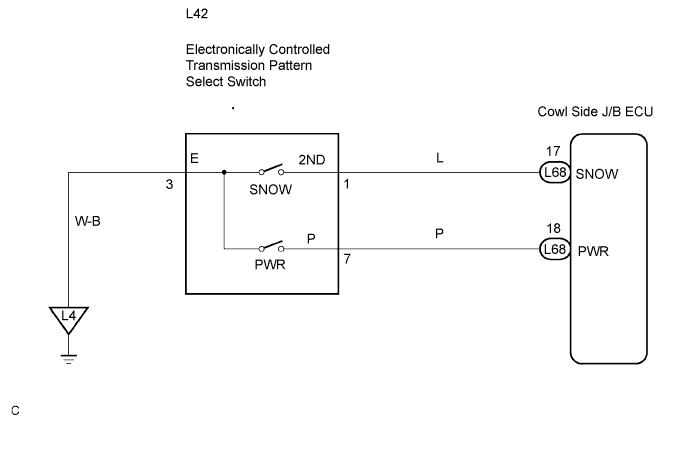
ELECTRONIC CONTROLLED AUTOMATIC TRANSMISSION SYSTEM > Pattern Select Switch Power Mode Circuit |
| 1.CHECK HARNESS AND CONNECTOR (PATTERN SELECT SWITCH ASSEMBLY - BODY GROUND) |
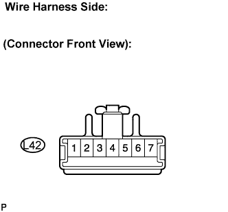
Disconnect the connector of pattern select switch.
 |
Measure the resistance according to the value(s) in the table below.
| Tester Connection | Specified Condition |
| 3 - Body ground | Below 1 Ω |
|
| ||||
| OK | |
| 2.INSPECT PATTERN SELECT SWITCH ASSEMBLY |
 |
Measure the resistance according to the value(s) in the table below.
| Switch Condition | Tester Connection | Specified Condition |
| Pattern select switch (PWR) | 3 - 7(*1) | Below 1 Ω |
| Pattern select switch (NORM) | ↑ | 10 kΩ or higher |
|
| ||||
| OK | |
| 3.CHECK HARNESS AND CONNECTOR (PATTERN SELECT SWITCH ASSEMBLY - MULTIPLEX NETWORK BODY ECU) |
 |
Connect the connector of pattern select switch.
Disconnect the cowl side junction block (multiplex network body ECU) connector.
Measure the resistance between terminal PWR of the cowl side junction block (multiplex network body ECU) and body ground.
| Switch Condition | Tester Connection | Specified Condition |
| Pattern select switch (PWR) | L68 - 18 (PWR) - Body ground | Below 1 Ω |
| Pattern select switch (NORM) | ↑ | 10 kΩ or higher |
|
| ||||
| OK | ||
| ||
