DTC C1715 Front Acceleration Sensor RH |
DTC C1716 Front Acceleration Sensor LH |
DTC C1717 Rear Acceleration Sensor |
DTC C1791 Front Acceleration Sensor RH (Test Mode DTC) |
DTC C1792 Front Acceleration Sensor LH (Test Mode DTC) |
DTC C1793 Rear Acceleration Sensor (Test Mode DTC) |
| DTC No. | DTC Detection Condition | Trouble Area |
| C1715 C1791 |
| Absorber control ECU (Houses right front acceleration sensor) |
| C1716 C1792 |
|
|
| C1717 C1793 |
|
|
| 1.READ VALUE OF INTELLIGENT TESTER |
Connect the intelligent tester to DLC3.
Turn the engine switch on (IG) and turn the intelligent tester main switch on.
Select "Data List" mode on the intelligent tester (Click here).
| Item | Measurement Item/ Range (Display) | Normal Condition | Diagnostic Note |
| G (Up & Down) Sensor FR | G (up & down) FR sensor reading / min.: -1045267.3 mm/s 2, max.: 1045299.2 mm/s2
| -8820 mm/s2 to 980 mm/s2 at still condition | Reading changes when the vehicle (FR) is bounced |
| G (Up & Down) Sensor FL | G (up & down) FL sensor reading / min.: -1045267.3 mm/s 2, max.: 1045299.2 mm/s2
| -8820 mm/s2 to 980 mm/s2 at still condition | Reading changes when the vehicle (FL) is bounced |
| G (Up & Down) Sensor Rear | G (up & down) rear sensor reading / min.: -1045267.3 mm/s 2, max.: 1045299.2 mm/s2
| -8820 mm/s2 to 980 mm/s2 at still condition | Reading changes when the vehicle (rear) is bounced |
Check that the value of the acceleration sensor read on the intelligent tester changes as the vehicle is bounced.
| Result | Proceed To |
| OK | A |
| NG (Front right) | A |
| NG (Front left) | B |
| NG (Rear) | C |
|
| ||||
|
| ||||
| A | |
| 2.RECONFIRM DTC |
Clear the DTC (Click here).
Perform a road test.
Check if the same DTC is detected (Click here).
| Result | Proceed To |
| DTC is output | A |
| DTC is output (When troubleshooting accordance with the PROBLEM SYMPTOMS TABLE) | B |
| DTC is not output | C |
|
| ||||
|
| ||||
| A | ||
| ||
| 3.INSPECT ACCELERATION SENSOR ASSEMBLY (LEFT FRONT) |
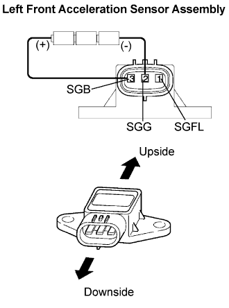 |
Remove the left front acceleration sensor assembly (Click here).
Connect 3 1.5 V dry batteries in series.
Connect terminal 3 (SGB) to the front battery's positive (+) terminal, and terminal 2 (SGG) to the rear battery's negative (-) terminal.
Measure the voltage according to the value(s) in the table below.
| Tester connection | Sensor condition | Voltage |
| SGFL (1) - SGG (2) | Sensor stationary | Approx. 2.3 V |
| SGFL (1) - SGG (2) | Sensor vibrating vertically | Change between approx. 1.0 to 4.0 V |
|
| ||||
| OK | ||
| ||
| 4.INSPECT ACCELERATION SENSOR ASSEMBLY (REAR) |
 |
Remove the rear acceleration sensor assembly (Click here).
Connect the 3 1.5 V dry batteries in series.
Connect terminal 3 (SGV) to the front battery's positive (+) terminal, and terminal 2 (SGND) to the rear battery's negative (-) terminal.
Measure the voltage according to the value(s) in the table below.
| Tester connection | Sensor condition | Voltage |
| SGRR (1) - SGND (2) | Sensor stationary | Approx. 2.3 V |
| SGRR (1) - SGND (2) | Sensor vibrating vertically | Change between approx. 1.0 to 4.0 V |
|
| ||||
| OK | |
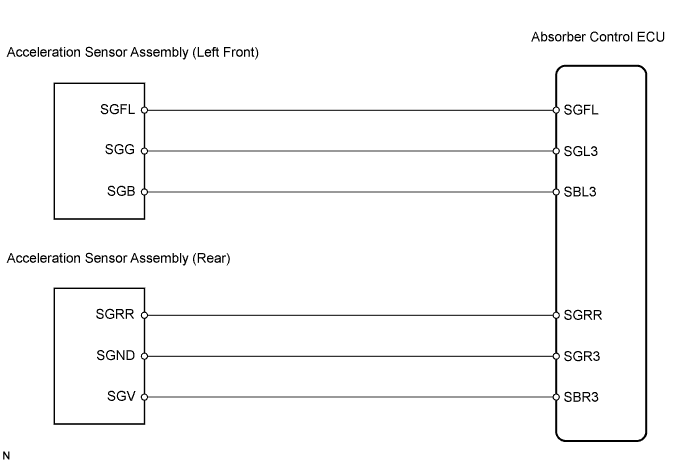
| 5.CHECK HARNESS AND CONNECTOR (ABSORBER CONTROL ECU TO ACCELERATION SENSOR ASSEMBLY) |
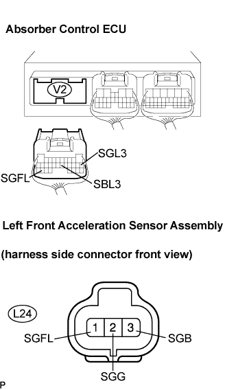 |
Front: (C1716, C1792)
Disconnect the absorber control ECU connector and acceleration sensor assembly connector.
Measure the resistance according to the value(s) in the table below.
| Tester connection | Specified condition |
| V2-29 (SGFL) - L24-1 (SGFL) | Below 1 Ω |
| V2-11 (SGL3) - L24-2 (SGG) | Below 1 Ω |
| V2-16 (SBL3) - L24-3 (SGB) | Below 1 Ω |
| V2-29 (SGFL) - Body ground | 10 kΩ or higher |
| V2-11 (SGL3) - Body ground | 10 kΩ or higher |
| V2-16 (SBL3) - Body ground | 10 kΩ or higher |
 |
REAR: (C1717, C1793)
Measure the resistance according to the value(s) in the table below.
| Tester connection | Specified condition |
| V2-27 (SGRR) - V26-1 (SGRR) | Below 1 Ω |
| V2-12 (SGR3) - V26-2 (SGND) | Below 1 Ω |
| V2-15 (SBR3) - V26-3 (SGV) | Below 1 Ω |
| V2-27 (SGRR) - Body ground | 10 kΩ or higher |
| V2-12 (SGR3) - Body ground | 10 kΩ or higher |
| V2-15 (SBR3) - Body ground | 10 kΩ or higher |
|
| ||||
| OK | |
| 6.RECONFIRM DTC |
Clear the DTC (Click here).
Perform a road test.
Check if the same DTC is detected (Click here).
| Result | Proceed To |
| DTC is output | A |
| DTC is output (When troubleshooting in accordance with the PROBLEM SYMPTOMS TABLE) | B |
| DTC is not output | C |
|
| ||||
|
| ||||
| A | ||
| ||
