DTC C1725 Front Damping Force Control Actuator RH Circuit |
DTC C1726 Front Damping Force Control Actuator LH Circuit |
DTC C1727 Rear Damping Force Control Actuator RH Circuit |
DTC C1728 Rear Damping Force Control Actuator LH Circuit |
| DTC No. | DTC Detection Condition | Trouble Area |
| C1725 |
|
|
| C1726 |
|
|
| C1727 |
|
|
| C1728 |
|
|
| 1.INSPECT ABSORBER CONTROL ACTUATOR OPERATION |
Connect the intelligent tester to DLC3.
Turn the engine switch on (IG) and turn the intelligent tester main switch on.
Select "Active Test" mode on the intelligent tester (Click here).
| Item | Vehicle Condition / Test Details | Diagnostic Note |
| Damper Step FR | Changes damper step / min.: 1 step, max.: 17 step | Shock absorber hardens as damper step increases |
| Damper Step FL | Changes damper step / min.: 1 step, max.: 17 step | Shock absorber hardens as damper step increases |
| Damper Step RR | Changes damper step / min.: 1 step, max.: 17 step | Shock absorber hardens as damper step increases |
| Damper Step RL | Changes damper step / min.: 1 step, max.: 17 step | Shock absorber hardens as damper step increases |
Check if the absorber control actuator operates to harden the suspension with the intelligent tester.
|
| ||||
| OK | |
| 2.RECONFIRM DTC |
Clear the DTC (Click here).
Perform a road test.
Check that the same DTC is recorded (Click here).
| Result | Proceed To |
| DTC is output | A |
| DTC is output (When troubleshooting accordance with the PROBLEM SYMPTOMS TABLE) | B |
| DTC is not output | C |
|
| ||||
|
| ||||
| A | ||
| ||
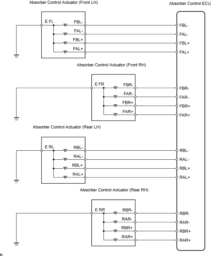
| 3.CHECK HARNESS AND CONNECTOR (ABSORBER CONTROL ACTUATOR CIRCUIT) |
 |
Disconnect the absorber control ECU connector and absorber control actuator connector.
Measure the resistance according to the value(s) in the table below.
| Tester Connection | Specified Condition |
| A39-5 (FAL+) - A12-2 (A+) | Below 1 Ω |
| A39-14 (FAL-) - A12-5 (A-) | Below 1 Ω |
| A39-6 (FBL+) - A12-1 (B+) | Below 1 Ω |
| A39-16 (FBL-) - A12-4 (B-) | Below 1 Ω |
| A39-5 (FAL+) - Body ground | 10 kΩ or higher |
| A39-6 (FBL+) - Body ground | 10 kΩ or higher |
| A39-14 (FAL-) - Body ground | 10 kΩ or higher |
| A39-16 (FBL-) - Body ground | 10 kΩ or higher |
| A12-3 (E) - Body ground | Below 1 Ω |
| Tester Connection | Specified Condition |
| A39-1 (FAR+) - A27-2 (A+) | Below 1 Ω |
| A39-2 (FAR-) - A27-5 (A-) | Below 1 Ω |
| A39-3 (FBR+) - A27-1 (B+) | Below 1 Ω |
| A39-4 (FBR-) - A27-4 (B-) | Below 1 Ω |
| A39-1 (FAR+) - Body ground | 10 kΩ or higher |
| A39-2 (FAR-) - Body ground | 10 kΩ or higher |
| A39-3 (FBR+) - Body ground | 10 kΩ or higher |
| A39-4 (FBR-) - Body ground | 10 kΩ or higher |
| A27-3 (E) - Body ground | Below 1 Ω |
| Tester Connection | Specified Condition |
| V2-6 (RAL+) - W27-2 (A+) | Below 1 Ω |
| V2-7 (RAL-) - W27-5 (A-) | Below 1 Ω |
| V2-8 (RBL+) - W27-1 (B+) | Below 1 Ω |
| V2-9 (RBL-) - W27-4 (B-) | Below 1 Ω |
| V2-6 (RAL+) - Body ground | 10 kΩ or higher |
| V2-7 (RAL-) - Body ground | 10 kΩ or higher |
| V2-8 (RBL+) - Body ground | 10 kΩ or higher |
| V2-9 (RBL-) - Body ground | 10 kΩ or higher |
| W27-3 (E) - Body ground | Below 1 Ω |
| Tester Connection | Specified Condition |
| V2-2 (RAR+) - V24-2 (A+) | Below 1 Ω |
| V2-3 (RAR-) - V24-5 (A-) | Below 1 Ω |
| V2-4 (RBR+) - V24-1 (B+) | Below 1 Ω |
| V2-5 (RBR-) - V24-4 (B-) | Below 1 Ω |
| V2-2 (RAR+) - Body ground | 10 kΩ or higher |
| V2-3 (RAR-) - Body ground | 10 kΩ or higher |
| V2-4 (RBR+) - Body ground | 10 kΩ or higher |
| V2-5 (RBR-) - Body ground | 10 kΩ or higher |
| V24-3 (E) - Body ground | Below 1 Ω |
|
| ||||
| OK | |
| 4.INSPECT ABSORBER CONTROL ACTUATOR (EACH ABSORBER CONTROL ACTUATOR) |
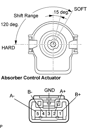 |
SHAFT STOP POSITION CHECK
Remove the absorber control actuator (Click here for front, Click here for rear).
Connect the connector to the absorber control actuator.
Check absorber control actuator operation (Click here).
ACTUATOR CHECK
Disconnect the absorber control actuator connector.
Measure the resistance according to the value(s) in the table below.
| Tester Connection | Specified Condition |
| 1 (B+) - 3 (GND) | 12.0 to 12.8 Ω |
| 2 (A+) - 3 (GND) | 12.0 to 12.8 Ω |
| 4 (B-) - 3 (GND) | 12.0 to 12.8 Ω |
| 5 (A-) - 3 (GND) | 12.0 to 12.8 Ω |
|
| ||||
| OK | |
| 5.RECONFIRM DTC |
Clear the DTC (Click here).
Perform a road test.
Check that the same DTC is recorded (Click here).
| Result | Proceed To |
| DTC is output | A |
| DTC is output (When troubleshooting accordance with the PROBLEM SYMPTOMS TABLE) | B |
| DTC is not output | C |
|
| ||||
|
| ||||
| A | ||
| ||
